How to Read Piping Isometric Drawings: The Complete Engineering Guide

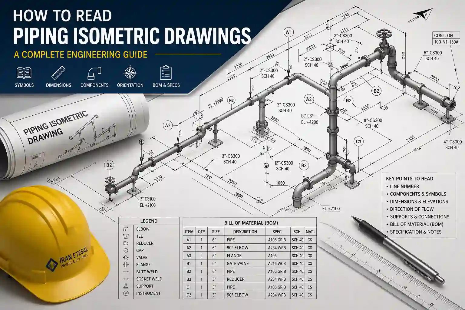
How to Read Piping Isometric Drawings – Complete Engineering Guide
Table of Contents
- 1. Introduction to Piping Isometric Drawings
- 2. What is a Piping Isometric Drawing?
- 3. Piping Isometric vs Other Drawing Types
- 4. Essential Components of a Piping Isometric
- 5. The Isometric Coordinate System
- 6. Understanding Dimensions in Isometrics
- 7. Piping Isometric Symbols Reference
- 8. Line Numbering and Pipe Specifications
- 9. The Bill of Material (BOM) in Isometrics
- 10. North Arrow, Elevation, and Orientation
- 11. Flow Direction and Slope Indicators
- 12. Shop Isometric vs Field Isometric
- 13. Weld Maps and Weld Numbering
- 14. Reading Pipe Supports and Hangers
- 15. Valves, Instruments, and Specialty Items
- 16. Insulation and Heat Tracing Symbols
- 17. The Drawing Title Block and Revision Block
- 18. Step-by-Step Isometric Interpretation
- 19. From Isometric to Fabrication: The Workflow
- 20. Construction and Installation Using Isometrics
- 21. Inspection and Quality Control Workflow
- 22. Isometrics in Stress Analysis
- 23. Common Engineering Mistakes
- 24. Best Practices and Engineer Tips
- 25. Industrial Recommendations
1. Introduction to Piping Isometric Drawings
In the industrial piping sector, the ability to accurately read and interpret piping isometric drawings is a fundamental skill that separates competent engineers from exceptional ones. These drawings serve as the primary communication tool between design offices, fabrication shops, and construction sites. A piping isometric drawing is essentially a three-dimensional representation of a piping system rendered on a two-dimensional medium, using a specialized projection technique that preserves key spatial relationships while presenting all critical fabrication and installation data in a single, readable format.
For engineers, inspectors, designers, and construction personnel, the piping isometric is the single most important document in the pipe fabrication and installation workflow. Unlike P&IDs, which show the functional logic of a system, or general arrangement drawings, which show broad layout, the isometric provides the exact dimensions, material specifications, weld details, and component information needed to manufacture and install a specific pipe assembly. This is why understanding how to read piping isometric drawings is a critical competency in the oil, gas, petrochemical, and power generation industries.
The isometric drawing bridges the gap between engineering design and physical reality. It translates the abstract lines of a P&ID into tangible, fabricable, and installable pipe spools. Every dimension, weld mark, and symbol on an isometric has a direct practical implication. A misread elevation can result in a pipe that does not align with equipment nozzles. An overlooked slope can lead to drainage problems. An incorrectly identified fitting can delay a project by weeks. This guide provides the comprehensive knowledge needed to avoid such errors and execute piping projects with precision and confidence.
2. What is a Piping Isometric Drawing?
A piping isometric drawing is a detailed, dimensioned, and annotated representation of a specific segment of a piping system. The term "isometric" is derived from the Greek words "isos" (equal) and "metron" (measure), reflecting the unique projection method where the three principal axes—X, Y, and Z—are drawn at 120-degree angles to each other. This creates a visual illusion of a three-dimensional object on a flat surface, allowing engineers to perceive the pipe's routing in space while simultaneously viewing all its critical dimensions.
Unlike orthographic projections, which show separate top, front, and side views, the isometric presents the entire pipe run in a single view. This single-view characteristic is precisely why isometrics are preferred for construction and fabrication. A fabricator can see the entire spool in one drawing, understand its orientation, and read all dimensions without having to mentally combine multiple drawings.
Each piping isometric typically represents a single pipe spool—a section of pipe that is fabricated in a shop and then transported to the field for installation. The isometric includes the pipe centerline, all fittings (elbows, tees, reducers, caps), flanges, valves, instruments, supports, and welds. It includes all dimensions required to fabricate the spool, including lengths between welds, center-to-end dimensions of fittings, and elevations relative to reference points. The isometric also carries critical engineering information such as the line number, pipe specification, insulation details, and heat tracing requirements.
A well-prepared piping isometric is a self-contained document. It provides everything needed to manufacture a spool—the pipe material, schedule, dimensions, fittings, weld requirements, and quality control criteria. This self-containment is why isometrics are the primary document in the pipe fabrication workflow.
3. Piping Isometric vs Other Drawing Types
To fully appreciate the role of the piping isometric, it is essential to understand how it differs from other drawing types used in piping projects. Each drawing serves a distinct purpose and contains different information. The following table provides a comprehensive comparison:
| Drawing Type | Purpose | Key Information | Primary User | 2D/3D |
|---|---|---|---|---|
| P&ID | Process control and instrumentation logic | Equipment, instruments, control loops, process flow, line sizes | Process engineers, operators | Schematic 2D |
| General Arrangement (GA) | Overall plant or area layout | Equipment locations, main pipe routing, structural steel, access ways | Layout engineers, construction planners | 2D plan and elevation views |
| Orthographic Drawing | Detailed pipe routing in plan and section views | Pipe routing dimensions, elevations, equipment connections | Piping engineers, detail designers | 2D multi-view |
| Isometric Drawing | Fabrication and installation of pipe spools | Spool dimensions, fittings, welds, BOM, line spec | Fabricators, construction teams, inspectors | Single-view 3D projection |
| Pipe Spool Drawing | Shop fabrication of pipe assembly | Detailed spool dimensions, weld map, material list | Fabrication shops | Isometric with spool breakdown |
The P&ID is the starting point of any piping design. It defines the process flow, the required line sizes, the types of valves and instruments, and the material specifications. However, the P&ID does not show how the pipes are routed in three-dimensional space. The P&ID is a schematic, not a spatial representation.
The GA drawing establishes the spatial framework. It shows where equipment is located, the main pipe racks, and the corridors for piping. However, the GA drawing is not detailed enough for fabrication. It does not contain the precise lengths of pipe segments or the exact locations of fittings and welds. The GA drawing is a planning document, not a construction document.
Orthographic drawings provide more detail, showing pipe routing in plan view and elevation views. But orthographic drawings require the viewer to interpret multiple drawings simultaneously to understand the three-dimensional routing. A fabricator would need to consult plan, front, and side views to assemble a complete picture—a time-consuming and error-prone process.
The isometric drawing solves this problem by presenting the complete pipe spool in a single drawing. The isometric contains all the spatial and dimensional information needed for fabrication and installation. This is why the isometric is the primary construction document. It is both detailed and comprehensive.
In modern engineering practice, the distinction between an isometric and a pipe spool drawing is often blurred. Many organizations use the terms interchangeably. However, a strict interpretation holds that an isometric is the initial drawing from the design office, while a pipe spool drawing is a refined version used by the fabrication shop, often breaking a large pipe run into manageable spools.
4. Essential Components of a Piping Isometric
A typical piping isometric drawing contains multiple layers of information. Understanding each component is the first step toward mastering isometric interpretation. Every element on an isometric is there for a reason, and missing any detail can lead to costly errors.
4.1 The Pipe Centerline
The pipe centerline is the backbone of the isometric drawing. It represents the path of the pipe through space, showing all changes in direction, elevation, and orientation. The centerline is drawn as a continuous heavy line, with elbows, tees, and reducers shown where the centerline changes direction or size. In an isometric, the centerline is always the reference from which all dimensions are measured. Understanding the centerline is fundamental to reading pipe isometric drawings.
4.2 Fittings and Components
Every component along the pipe centerline is shown on the isometric. Standard pipe fittings such as elbows, tees, reducers, and caps are drawn using standard symbols. Flanges are shown as short, thick lines perpendicular to the pipe centerline. Valves are shown using their standard symbol. Instruments are shown with their associated instrument symbols. Each component is labeled with its size, type, and specification, ensuring that the fabricator can select the correct part.
4.3 Dimensions and Tolerances
Dimensions are the most critical element of the isometric. They must be complete and unambiguous. The isometric shows the length of every straight pipe segment between components, the center-to-end dimensions of all fittings, and the overall dimensions of the completed spool. Flanges are dimensioned from face to face. Welds are dimensioned from weld centerline to weld centerline or from weld to fitting center. All dimensions must be referenced to clear start and end points to eliminate ambiguity.
4.4 Bill of Material (BOM)
The Bill of Material is an essential part of the isometric. It lists every component required to fabricate the spool, including pipe material, fittings, flanges, valves, and supports. The BOM includes the quantity, size, material specification, and schedule of each component. For example, a BOM might list "1 ea, 6" x 4" Reducer, ASTM A234 WPB, SCH 40." Without a complete and accurate BOM, the fabricator cannot order the correct materials.
4.5 Welding and Inspection Information
The isometric identifies all field and shop welds. Each weld is numbered and marked on the drawing. The weld number references a weld map that may be provided on the same drawing or in a separate document. Welding specifications, including preheat requirements, interpass temperature controls, and post-weld heat treatment (PWHT) requirements, are often included in the drawing notes. The isometric also may include inspection requirements, such as the extent of radiographic or ultrasonic testing required for each weld.
4.6 Support Details
Pipe supports are shown on the isometric at the locations where they must be attached. Support type, size, and elevation are indicated. This information is critical for both fabrication and installation, as supports must be in the correct location to provide the necessary structural integrity. Additional support details, such as clamps, shoes, or guides, are specified in the notes or on a separate support drawing referenced in the isometric.
4.7 Notes and Engineering Information
The isometric contains notes that provide critical engineering information not otherwise shown in the drawing. This includes the line number, pipe specification, insulation and heat tracing requirements, hydrostatic test pressure, and any special instructions. The notes may also reference other documents, such as the P&ID, the stress analysis report, or the project specifications. These notes should be read and understood before any fabrication or construction work begins.
5. The Isometric Coordinate System
The power of the piping isometric lies in its ability to represent three-dimensional space using a two-dimensional projection. This is achieved using a specific coordinate system that fixes the pipe's location in space. Understanding this coordinate system is critical to reading piping isometric drawings accurately.
In an isometric projection, the three principal axes—North-South (X-axis), East-West (Y-axis), and Vertical (Z-axis)—are drawn at 120 degrees to each other. This creates the characteristic hexagonal appearance of an isometric drawing. The actual orientation of the drawing on the page is determined by the chosen projection, but the spatial relationships between points on the drawing preserve their relative positions in real space.
The coordinate system is typically established using an origin point, which is often the centerline of a piece of equipment or a structural steel column. All locations on the isometric are referenced to this origin. Coordinates may be given in the format X=12, Y=16, Z=20, indicating distances in meters or feet from the origin along each axis. This coordinate system is essential for stress analysis, ensuring that the pipe aligns with equipment and supports.
Elevation is always measured on the vertical (Z) axis. The elevation is typically referenced to a plant datum, such as the finished floor level or the top of a foundation. All elevations on the isometric are shown relative to this datum. It is crucial to understand the elevation reference to avoid alignment issues at equipment connections.
The coordinate system also helps identify the location of each weld and component. For example, a weld at X=10, Y=15, Z=20 is at a specific point in three-dimensional space. This allows the construction team to locate the weld in the field and ensures that all spools fit together correctly.
6. Understanding Dimensions in Isometrics
Dimensions are the lifeblood of piping isometric drawings. Without accurate dimensions, a pipe spool cannot be fabricated. The ability to correctly interpret and verify dimensions is one of the most important skills in reading piping isometric drawings.
6.1 Types of Dimensions
Piping isometrics use several types of dimensions, each with a specific purpose. The most common are:
- Center-to-Center Dimensions: The distance between the center points of two fittings or components. This is the most common dimension on an isometric. For example, the dimension between the center of an elbow and the center of a flange.
- Center-to-End Dimensions: The distance from the center of a fitting to its end. This is used to dimension the position of fittings such as elbows and tees. The center-to-end dimension is provided in standards such as ASME B16.9.
- End-to-End Dimensions: The distance between the ends of two components. For example, the distance between two flanges.
- Face-to-Face Dimensions: The distance between the faces of two flanges. This is used when specifying the length of a valve or a short pipe spool.
- Overall Dimensions: The total length of the pipe spool, measured from its outermost points. This is used for logistics and to verify that the spool fits within its planned location.
- Elevation Dimensions: The vertical distance from a reference plane to a point on the pipe. This may be the elevation of the pipe centerline, the elevation of a flange face, or the elevation of a support.
- Coordinate Dimensions: The X, Y, and Z coordinates of a point in the plant coordinate system. This is used to locate the pipe in space.
6.2 Dimension Reference Points
Every dimension on an isometric must be referenced to a clear, unambiguous point. Common reference points include:
- Weld Centerlines: The center of a weld is a frequent reference point because it represents a known location on the pipe.
- Fitting Centers: The center of an elbow or tee is a critical reference point.
- Flange Faces: The face of a flange is a standard reference point for dimensional measurements, especially for valves and instruments.
- Pipe Ends: The physical end of a pipe segment or spool is a clear reference point.
- Equipment Nozzles: The centerline of an equipment nozzle is a key reference point for connecting the pipe to the equipment.
6.3 Dimension Lines and Leaders
Dimensions are typically shown with dimension lines and leaders. The dimension line is a line drawn parallel to the distance being measured, with arrowheads at each end. A leader is a line that connects the dimension to the point being measured. The dimension value is written along the dimension line, often with a prefix such as "L=," "D=," or "E=" to indicate the type of dimension. Reading these carefully is essential for accurate fabrication.
6.4 Slope and Fall Dimensions
In gravity flow systems, pipes are often sloped to allow for drainage. The isometric indicates the slope direction and magnitude. This may be shown as a dimension along the pipe, with an arrow indicating the direction of fall, or as a slope ratio such as 1:100 or 1/8" per foot. Proper interpretation of slope is critical to ensure that the system functions as designed.
7. Piping Isometric Symbols Reference
Piping isometric drawings rely on a standard set of symbols to represent various components. These symbols are essential for communicating the design without cluttering the drawing with excessive details. Understanding these symbols is fundamental to reading piping isometric drawings.
7.1 Pipe Fitting Symbols
Pipe fittings are represented by simple geometric symbols. The most common fitting symbols are:
| Fitting | Symbol Description |
|---|---|
| Elbow (90° LR) | A curved line representing a 90-degree turn |
| Elbow (45°) | A curved line representing a 45-degree turn |
| Tee (Equal) | A T-shaped intersection |
| Tee (Reducing) | A T-shaped intersection with different line sizes |
| Reducer (Concentric) | A tapered section |
| Reducer (Eccentric) | A tapered section with offset centerline |
| Cap | A line across the end of the pipe |
| Flange | A short, thick line perpendicular to the pipe |
| Stub End | A line with a flared end |
7.2 Valve Symbols
Valves are shown using standard valve symbols. The symbol differs by valve type:
| Valve Type | Symbol Description |
|---|---|
| Gate Valve | A line with a small box at the center |
| Globe Valve | A line with a circle and a short line through it |
| Check Valve | A line with a circle containing an arrow |
| Ball Valve | A line with a box and a diagonal line |
| Butterfly Valve | A line with a circle at the center |
| Needle Valve | A small circle with a line through it |
7.3 Support Symbols
Pipe supports are shown with symbols indicating the type of support:
| Support Type | Symbol Description |
|---|---|
| Shoe Support | A line with a small box under the pipe |
| Guide Support | A line with arrows indicating guided direction |
| Spring Support | A line with a zigzag symbol |
| Rod Hanger | A line with a circle at the top |
| Clamp Support | A line with a C-shaped symbol |
7.4 Instrument Symbols
Instruments are shown with standard instrument symbols, often indicating whether the instrument is field-mounted or panel-mounted. The symbol includes the instrument function and location code.
7.5 Weld Symbols
Welds on an isometric are shown with a specific symbol that indicates the weld type and location. Groove welds are shown with a V-shaped symbol. Fillet welds are shown with a triangular symbol. The weld symbol includes a reference number that links to a weld map or a welding procedure specification. The weld map is essential for quality control and inspection.
8. Line Numbering and Pipe Specifications
The line number is the unique identifier for a specific pipe run in a process plant. It is the single most important piece of information on a piping isometric, as it ties the drawing to the P&ID, the pipe specification, and the material requisition. Understanding the line numbering system is essential for reading piping isometric drawings correctly.
A typical line number follows a standard format. It generally includes:
- Plant Area or Unit Number: Identifies the plant area where the line is located.
- Line Size: The nominal pipe size (NPS) of the pipe, such as 6" or 8".
- Service Code: A code identifying the fluid service, such as HC (Hydrocarbon), ST (Steam), or WW (Waste Water).
- Pipe Specification: A code identifying the material specification, schedule, and pressure rating.
- Sequential Number: A unique number identifying the specific line within the service and specification.
For example, a line number might be: 100-6"-HC-400-F1. In this example, "100" is the unit number, "6" is the line size, "HC" is the service (hydrocarbon), "400" is a reference to the pipe specification, and "F1" is a sequential identifier.
The pipe specification referenced in the line number contains all the material details for the pipe and fittings. The specification defines the material grade (e.g., ASTM A106 Gr. B for pipe, ASTM A234 WPB for fittings), the pipe schedule (e.g., SCH 40, SCH 80), the flange rating (e.g., Class 150, Class 300), and the valve types. The pipe specification must be available to the fabricator and construction team to ensure that the correct materials are used. For information on common pipe schedules and their applications, refer to our SCH 40 vs SCH 80 comparison guide.
The line number is shown prominently on the isometric, typically in a box or near the title block. The line number is also referenced on the BOM, ensuring that all materials are consistent with the specification. It is critical to verify that the line number on the isometric matches the line number on the P&ID and the material requisition.
9. The Bill of Material (BOM) in Isometrics
The Bill of Material (BOM) is an essential part of every piping isometric. It provides a comprehensive list of all components required to fabricate the pipe spool. The BOM ensures that the fabricator has the correct materials and that the material procurement process is efficient and error-free.
A typical BOM includes:
- Item Number: A unique reference number for each component type on the drawing.
- Quantity: The number of each component required.
- Description: A clear description of the component, including the type, size, and material specification.
- Material Specification: The ASTM, ASME, or other standard specification for the component.
- Notes: Any special requirements, such as special heat treatment or testing.
The BOM is typically placed on the isometric drawing, often in a table format. The table may be located in the lower right or lower left corner of the drawing. The BOM is cross-referenced to the drawing by the item numbers shown next to each component on the isometric.
For example, the BOM for a simple spool might show:
| Item | Qty | Description | Specification |
|---|---|---|---|
| 1 | 1 | Pipe, 6" SCH 40, ASTM A106 Gr. B | 6"-SCH40-A106B |
| 2 | 2 | Elbow 90° LR, 6" SCH 40, ASTM A234 WPB | 6"-SCH40-A234WPB |
| 3 | 1 | Flange, 6" CL150, ASTM A105 | 6"-CL150-A105 |
The BOM must be reviewed and verified by the fabricator before any work begins. Any discrepancies between the BOM and the isometric can lead to fabrication errors and costly rework. It is also common practice to verify the BOM against the material procurement list. For more information on procurement processes, see our Welding Fittings Procurement Guide.
A key element of the BOM is the correct identification of pipe fittings. For example, specifying the correct elbow type (LR vs SR) is critical. For more details, refer to our guide on LR vs SR elbows. Additionally, understanding the manufacturing methods, such as the difference between seamless and welded elbows, is important for material selection. For comprehensive dimensions, see our pages on elbow dimensions and tee dimensions.
10. North Arrow, Elevation, and Orientation
Orientation is a critical aspect of any piping isometric. The isometric must clearly indicate the direction of North, the elevation of the pipe, and the orientation of the pipe in plan view. This information ensures that the spool is installed in the correct location and with the correct alignment.
10.1 The North Arrow
The North arrow on the isometric establishes the orientation of the drawing relative to the plant's North. The North arrow is usually a simple arrow, often with an "N" next to it. The arrow may point in any direction on the drawing, but the orientation of the arrow must be consistent with the project's coordinate system. Understanding the North arrow is essential for correctly orienting the pipe spool during installation.
10.2 Elevation
Elevation is the vertical location of the pipe relative to a reference point. The elevation is typically shown on the isometric at key points, such as at flanges, at the centerline of the pipe, or at support locations. Elevations are critical for ensuring that the pipe aligns with equipment nozzles and with other pipe systems. If an elevation is misread, the pipe may not fit, requiring significant rework.
Elevation is often shown with an "EL" prefix, followed by the elevation value. The reference point for elevation is usually a plant datum, such as the top of the concrete foundation or the finished floor level. The isometric should clearly state the elevation reference point. Common reference points are "EL 100.0" or "EL +12.5 m." Elevations are measured on the vertical (Z) axis of the coordinate system.
10.3 Orientation Symbols
The isometric may use orientation symbols to indicate the orientation of specific components. For example, an eccentric reducer may have a symbol indicating the orientation of the flat side. A flange may have a symbol indicating the orientation of the bolt holes. These symbols are critical for ensuring that the spool is installed correctly and that the components function as designed.
Orientation is particularly important for components that are not symmetrical, such as eccentric reducers. An eccentric reducer installed upside-down can lead to fluid accumulation and operational problems. The isometric orientation symbols prevent such errors.
11. Flow Direction and Slope Indicators
Flow direction and slope are critical elements of piping design, particularly for gravity flow systems and systems where fluid movement is essential. Accurately reading these indicators on an isometric is vital for proper installation and system function.
11.1 Flow Direction
The flow direction is typically shown on the isometric using an arrow. The arrow indicates the direction of fluid flow through the pipe. The flow arrow may be on the pipe centerline or next to it. The flow direction is essential for installing check valves, which must be oriented in the correct direction. The flow direction also helps the construction team to understand the system operation, especially during hydrotesting and flushing.
11.2 Slope Indicators
In systems where gravity drainage is required, the pipe is installed with a slope. The slope is indicated on the isometric using a slope symbol or a slope dimension. The slope symbol is typically a small triangle or an arrow indicating the direction of the fall. The magnitude of the slope is given as a percentage or as a ratio, such as 1:100 or 1/8" per foot. The isometric includes the slope at the start and end of the sloped pipe section, ensuring that the pipe is installed with the correct fall.
Slope is critical for system drainage and for preventing fluid accumulation in low points. A pipe installed without the correct slope may trap fluid, leading to operational problems, corrosion, or freezing. Therefore, it is essential to read and understand the slope indicators on the isometric.
12. Shop Isometric vs Field Isometric
Piping isometrics are typically divided into two categories: shop isometrics and field isometrics. Each has a distinct purpose and is used by different teams. Understanding the difference between shop and field isometrics is important for effective project execution.
12.1 Shop Isometric
A shop isometric is a drawing created for fabrication in a workshop. The shop isometric breaks the pipe run into manageable spools that can be fabricated in the shop and then transported to the field for installation. The shop isometric is highly detailed, showing all dimensions, welds, and material specifications. The shop isometric is used by the fabrication shop to manufacture the pipe spool.
Shop isometrics typically include:
- Detailed dimensions of each straight pipe segment.
- Center-to-end dimensions of all fittings.
- Weld numbers and locations.
- Material specifications for all components.
- A Bill of Material.
- Identification of shop welds that will be made in the fabrication shop.
12.2 Field Isometric
A field isometric is a drawing created for installation at the construction site. The field isometric shows how the pipe spools are assembled in the field. The field isometric includes the same level of detail as the shop isometric, but it focuses on the connections between spools and the connection to equipment. The field isometric is used by the construction team to install the pipe.
Field isometrics typically include:
- Overall dimensions of the pipe assembly.
- Elevations and coordinates of key points.
- Identification of field welds that will be made on-site.
- Support details and locations.
- Connection details to equipment and other pipe systems.
12.3 The Isometric to Spooling Process
The design office creates the isometric based on the P&ID and the 3D model. The isometric is then sent to the fabrication shop. The fabrication shop reviews the isometric and may break it into smaller spools based on the shop's fabrication capabilities and the logistics of transporting the spools to the site. This process is called spooling. Each spool is then assigned a unique spool number. The spool drawings are then sent to the construction site, where the field team installs the spools.
13. Weld Maps and Weld Numbering
Weld maps and weld numbering are essential components of piping isometrics. They provide a systematic approach to identifying, documenting, and inspecting each weld on the pipe run. A clear understanding of weld maps is essential for quality control and for ensuring that all welds are performed and inspected according to the project specifications.
13.1 Weld Numbering
Each weld on an isometric is assigned a unique number. The weld number is typically a combination of a prefix or suffix indicating whether the weld is a shop weld (SW) or a field weld (FW), followed by a sequential number. For example, W-101, SW-201, or FW-301. The weld number is shown on the isometric adjacent to the weld symbol. The weld number is used to track the weld through the fabrication and construction process.
13.2 The Weld Map
The weld map is a record of all welds on the isometric. The weld map may be a simple list or a separate drawing showing the location of each weld on the pipe run. The weld map includes the weld number, the weld type, the pipe material, the welding procedure specification (WPS), and the inspection requirements. The weld map is a critical document for quality control.
13.3 Field Welds vs Shop Welds
The isometric clearly identifies whether each weld is a shop weld or a field weld. Shop welds are made in the fabrication shop under controlled conditions. Field welds are made on the construction site. The distinction is important because field welds are generally more difficult to make and inspect due to site conditions. Field welds often require additional NDT, such as radiographic testing (RT), and may require post-weld heat treatment (PWHT) if specified in the project requirements. Understanding this distinction is vital for planning the inspection and quality control workflow.
14. Reading Pipe Supports and Hangers
Pipe supports are essential for maintaining the structural integrity of a piping system. The isometric drawing shows the location and type of each pipe support. Correct interpretation of support symbols is crucial for ensuring that the pipe is properly supported and that the loads are correctly transferred to the structure.
14.1 Support Symbols
Supports are shown on the isometric using standard symbols. The symbol indicates the type of support, such as a shoe support, a guide, a spring hanger, or a rod hanger. The support is shown at the location where it must be attached to the pipe. The elevation of the support is also provided, to ensure that it is installed at the correct height. For more detailed support information, a separate support drawing may be referenced.
14.2 Support Details
The isometric may include a support detail or reference to a support detail drawing. The support detail provides additional information about the support, such as the size and type of clamp, the bolt size, and the connection to the supporting structure. The support detail ensures that the correct support is used and that it is installed correctly.
Pipe supports are critical for preventing pipe sagging, vibration, and excessive stress on equipment nozzles. Incorrectly installed supports can lead to pipe failure. Therefore, understanding support symbols and details is essential for reading piping isometric drawings.
15. Valves, Instruments, and Specialty Items
Valves, instruments, and specialty items are critical components of a piping system. The isometric drawing shows the location and type of each of these items. Correct identification and interpretation of these symbols is essential for proper system functionality.
15.1 Valve Symbols
Valves are shown using standard valve symbols. The symbol indicates the type of valve, such as gate, globe, check, ball, or butterfly. The valve symbol includes the valve size, pressure rating, and material specification. The valve operator is also shown if it is accessible or requires special attention during installation. The valve position—whether it is normally open, normally closed, or throttled—may also be indicated.
15.2 Instrument Symbols
Instruments are shown using standard instrument symbols. The symbol indicates the type of instrument, such as a pressure gauge, temperature gauge, flow meter, or level indicator. The instrument symbol includes the instrument tag number, which ties the instrument to the P&ID and the instrument data sheet. The location of the instrument—whether it is field-mounted or panel-mounted—is also shown.
15.3 Specialty Items
Specialty items, such as strainers, sight glasses, expansion joints, and steam traps, are shown on the isometric using their standard symbols. The symbol includes the item size, pressure rating, and material specification. The isometric may also include a note referencing a separate data sheet or installation detail for the specialty item.
It is essential to verify that all valves, instruments, and specialty items on the isometric are correctly identified and that the correct items are ordered and installed. For more information on valve and fitting selection, see our comprehensive guide on butt weld fittings.
16. Insulation and Heat Tracing Symbols
Insulation and heat tracing are important for maintaining process temperature and for protecting personnel. The isometric drawing shows the type and extent of insulation and heat tracing on the pipe. Correct interpretation of these symbols is essential for proper installation.
16.1 Insulation Symbols
Insulation is shown on the isometric using a symbol that indicates the type and thickness of the insulation. The symbol may be a dashed line around the pipe or a specific pattern. The insulation symbol includes a reference to an insulation specification, which provides detailed information about the insulation material and installation requirements. The insulation symbol also indicates the extent of the insulation, showing where the insulation starts and ends on the pipe run.
16.2 Heat Tracing Symbols
Heat tracing is shown on the isometric using a symbol that indicates the type of heat tracing, such as electric tracing or steam tracing. The heat tracing symbol includes a reference to a heat tracing specification. The heat tracing specification provides details about the tracing cable or tubing, the power or steam supply, and the installation requirements. The heat tracing symbol also shows the location of the heat tracing components, such as power connection points or steam traps.
Proper insulation and heat tracing are critical for process systems. Incorrectly installed insulation or heat tracing can lead to process upsets, safety hazards, or energy losses. Therefore, it is essential to read and understand the insulation and heat tracing symbols on the isometric.
17. The Drawing Title Block and Revision Block
The title block and revision block provide essential administrative and quality control information about the isometric drawing. These blocks are typically located in the lower right or lower left corner of the drawing. Understanding the information in these blocks is essential for ensuring that the correct drawing is being used for fabrication and construction.
17.1 Title Block Information
The title block typically includes the following information:
- Project Name and Number: The name and number of the overall project.
- Plant or Unit Name: The specific plant or unit where the pipe is located.
- Drawing Title: A description of the drawing, such as "Piping Isometric."
- Drawing Number: A unique identification number for the drawing.
- Line Number: The line number of the pipe shown on the isometric.
- Scale: The scale of the drawing. Isometrics are typically not drawn to scale, but a scale may be indicated for reference.
- Drawing Date: The date the drawing was prepared.
- Designer and Checker: The names of the individuals who prepared and checked the drawing.
- Approval: The signature or initials of the approving authority.
17.2 Revision Block Information
The revision block tracks the changes made to the drawing over time. The revision block typically includes:
- Revision Number: A sequential number or letter identifying the revision.
- Description: A brief description of the changes made in the revision.
- Date: The date the revision was made.
- Prepared, Checked, and Approved: The names or initials of the individuals involved in the revision.
18. Step-by-Step Isometric Interpretation
Reading a piping isometric drawing is a skill that can be learned through a systematic approach. The following step-by-step process provides a practical method for interpreting any piping isometric. This process can be applied by engineers, fabricators, inspectors, and construction personnel.
Step 1: Review the Title Block
Begin by reviewing the title block to understand the project context, the drawing number, the line number, and the revision status. This establishes the administrative context and ensures that the correct drawing is being used.
Step 2: Identify the Line Number
Locate the line number on the drawing. Verify that the line number matches the line number on the P&ID and the project's line list. This ensures that the isometric corresponds to the correct process line.
Step 3: Understand the Pipe Specification
Identify the pipe specification from the line number or from the drawing notes. Review the pipe specification to understand the material requirements, pipe schedule, and flange ratings. This information is essential for material procurement and fabrication. For an overview of pipe schedules, see our article on NPS and Pipe Schedule.
Step 4: Locate the North Arrow and Elevation Reference
Find the North arrow and the elevation reference point on the drawing. This establishes the orientation and vertical location of the pipe. Understanding these references is essential for field installation and for ensuring that the pipe aligns with equipment and structures.
Step 5: Trace the Pipe Centerline
Follow the pipe centerline from the start to the end of the spool. Note the direction changes and the fittings where direction changes occur. Identify the routing of the pipe and the overall flow path. Pay attention to the line breaks that indicate where the spool connects to other spools or to equipment.
Step 6: Identify All Components
Identify all components on the isometric, including fittings, flanges, valves, instruments, and supports. Use the project's symbol legend to ensure correct identification. Verify the size and type of each component.
Step 7: Read the Dimensions
Read all dimensions on the isometric, starting from a known reference point. Verify that the dimensions are complete and unambiguous. Check the center-to-center, center-to-end, end-to-end, and overall dimensions. Verify the dimensions against the project's dimensional standards. Pay close attention to slope dimensions for gravity flow systems.
Step 8: Identify the Welds
Locate all welds on the isometric. Determine whether each weld is a shop weld or a field weld. Verify the weld numbers and the associated welding procedure specification. This is critical for planning quality control and inspection.
Step 9: Review the Bill of Material
Review the Bill of Material (BOM) and verify that it includes all components shown on the drawing. Check that the quantities, sizes, and material specifications are correct. Cross-reference the BOM with the material procurement list to ensure that all required materials are available.
Step 10: Read the Drawing Notes
Read all notes on the drawing. The notes often contain critical information that is not otherwise shown, such as special inspection requirements, heat treatment requirements, insulation details, and hydrostatic test requirements. Ignoring the notes can lead to construction errors.
Step 11: Review the Revision Block
Review the revision block to ensure that the drawing is the latest revision. Verify that all changes have been incorporated and that the drawing is consistent with the other project documents. This is a critical step in quality control.
19. From Isometric to Fabrication: The Workflow
The piping isometric drawing is the primary document that drives the pipe fabrication workflow. Understanding this workflow is essential for project planning and execution. The following steps outline a typical fabrication workflow based on the isometric.
19.1 Design and Isometric Generation
The workflow begins with the engineering design phase. The piping designer creates the isometric based on the P&ID, the 3D model, and the project specifications. The isometric is generated using specialized software, such as CADWorx, SmartPlant, or AutoPIPE. The generated isometric is then reviewed and approved by the lead engineer.
19.2 Isometric Review and Verification
The isometric is reviewed by the fabrication and construction teams. The review verifies that the dimensions are complete, the BOM is accurate, and the material specifications are correct. The review also checks for any constructability issues, such as tight spaces or difficult access for welding. This step is essential for preventing errors before fabrication begins. Fabrication-specific considerations, such as the manufacturing process of butt weld fittings, may be reviewed.
19.3 Material Procurement
The BOM from the isometric is used to generate a material requisition. The materials are ordered from suppliers and delivered to the fabrication shop. The fabrication shop verifies the material delivery against the BOM. Any discrepancies are resolved before fabrication begins. Understanding how to detect fake welding fittings is important during procurement.
19.4 Spooling and Shop Fabrication
The fabrication shop reviews the isometric and determines the best way to break the pipe run into individual spools. The shop creates spool drawings for each spool. The spool is then fabricated in the shop, following the dimensions and specifications on the isometric. The fabrication process includes cutting, beveling, fitting, and welding. The shop also performs quality control inspections, such as visual inspection and dimensional verification. The shop may also perform hydrostatic testing of the fabricated spool.
19.5 Quality Control and Inspection
As the spools are fabricated, they undergo quality control inspections. The inspections verify that the dimensions are correct, the welds meet the specifications, and the material is correct. The inspection records are documented and attached to the spool. This documentation is essential for the final project handover. The inspection process is guided by the weld map and the quality requirements on the isometric. Refer to our case study on welded joint leaks for practical lessons on quality.
19.6 Shipping and Logistics
The fabricated spools are prepared for shipping. The spools are cleaned, coated, and protected for transport. The shipping plan considers the size and weight of the spools, as well as the delivery schedule. The spools are delivered to the construction site in the order required for installation.
19.7 Field Installation
At the construction site, the field team receives the spools and installs them according to the field isometric. The field team uses the isometric to locate the spool, align it with the equipment, and connect it to the adjacent spools. The field team performs the field welds and completes the installation. The installation is guided by the field isometric and the field notes.
19.8 Final Testing and Handover
After installation, the pipe system is hydrostatically tested to verify its integrity. The isometric provides the test pressure and the duration of the test. The test results are documented. After the successful test, the system is handed over to the operations team. For an understanding of the global context, review our analysis of the global steel market for butt weld fittings.
20. Construction and Installation Using Isometrics
The field isometric is the primary document used by the construction team for pipe installation. The field isometric provides the information needed to install the spool correctly, including location, orientation, and connection details. The construction team must be proficient in reading piping isometric drawings to ensure a successful project.
20.1 Site Preparation
Before the pipe spools arrive, the construction site is prepared. The foundations, structural steel, and equipment are installed. The isometric is used to verify that the equipment nozzles are in the correct locations and that the structural steel provides adequate support for the pipe.
20.2 Spool Receiving and Verification
When the spools arrive on site, the construction team verifies that the spools match the isometric. The team checks the spool dimensions, the fittings, and the flange connections. The team also verifies the material certification and the inspection records. Any discrepancies are reported immediately.
20.3 Spool Installation
The spools are installed according to the field isometric. The team uses the isometric to identify the location and orientation of each spool. The spools are hoisted into place and connected to the adjacent spools and equipment. Field welds are made as required. The isometric provides the weld details and the inspection requirements.
20.4 Support Installation
The pipe supports are installed according to the isometric. The supports are located at the specified positions and installed at the correct elevation. The supports are critical for ensuring the pipe's stability and for preventing stress on the equipment nozzles.
20.5 Final Alignment and Adjustment
After the spools are connected, the pipe system is aligned. The alignment is checked against the isometric. The elevations and the coordinates are verified. Any adjustments are made to ensure that the pipe is in the correct position and that it is aligned with the equipment.
20.6 Hydrostatic Testing Preparation
After the installation is complete, the pipe system is prepared for hydrostatic testing. The isometric is used to identify the test points and the test pressure. The system is filled with water and pressurized to the test pressure. The isometric is used to verify that all valves and instruments are in the correct position for the test.
For additional guidance on field construction, see our piping maintenance and repair guide. If you need specialized design or analysis tools, visit our piping engineering tools page.
21. Inspection and Quality Control Workflow
Quality control is a critical part of the piping construction process. The isometric is the primary document used for inspection and quality control. The following steps outline a typical inspection workflow based on the isometric.
21.1 Material Inspection
The first step in quality control is material inspection. The inspector checks the materials against the BOM on the isometric. The inspector verifies the material grade, the size, the schedule, and the material certification. The inspector also checks for any visible damage to the materials. This is a critical step for preventing material-related failures. The quality of the fittings themselves is crucial; refer to our guide on elbow manufacturing methods for quality insights.
21.2 Dimensional Inspection
The next step is dimensional inspection. The inspector checks the dimensions of the fabricated spools against the isometric. The inspector measures the pipe lengths, the center-to-center dimensions, the center-to-end dimensions, and the overall dimensions. The inspector also checks the flange alignment and the bolt hole orientation. Any dimensional discrepancies are corrected before the spool is installed. Understanding the dimensions of standard fittings, such as reducers, is essential.
21.3 Weld Inspection
Weld inspection is the most critical part of the quality control process. The inspector checks all welds against the weld map and the welding procedure specification. The inspector performs visual inspection of all welds. The inspector may also perform non-destructive testing, such as radiography or ultrasonic testing, based on the inspection requirements. The inspector documents the inspection results and verifies that the welds meet the project specifications.
21.4 Support Inspection
The inspector checks the pipe supports against the isometric. The inspector verifies that the supports are in the correct location and that they are installed correctly. The inspector checks the support material and the attachment to the pipe and structure. The inspector also verifies that the supports provide the correct level of restraint or flexibility.
21.5 Documentation
All inspection results are documented and attached to the isometric. This documentation provides a complete record of the quality control process. The documentation is essential for the final project handover and for the long-term management of the plant. The documentation includes material test reports, dimensional inspection reports, weld inspection reports, and test reports.
22. Isometrics in Stress Analysis
Piping isometrics are essential for stress analysis. The stress analysis engineer uses the isometric to build a finite element model of the piping system. The model is used to calculate the stresses in the pipe, the loads on the supports, and the nozzle loads on the equipment. Accurate stress analysis is essential for ensuring the safety and reliability of the piping system.
22.1 Data Required from Isometric
The stress analysis engineer extracts the following data from the isometric:
- The pipe centerline path.
- The coordinates of all bends and fittings.
- The dimensions of all straight pipe segments.
- The elevations of all key points.
- The type and location of all supports.
- The location and type of all equipment connections.
- The pipe schedule and material specification.
- The design temperature and pressure.
22.2 Stress Analysis Workflow
The stress analysis workflow typically involves the following steps:
- Model Building: The engineer builds a model of the piping system based on the isometric data.
- Load Application: The engineer applies the design loads, including weight, pressure, temperature, and seismic loads.
- Analysis: The engineer runs the analysis and calculates the stresses, displacements, and loads.
- Code Checking: The engineer checks the results against the allowable stress limits in the applicable code, such as ASME B31.3.
- Support Design: The engineer designs the pipe supports based on the calculated loads.
- Optimization: The engineer may adjust the pipe routing or the support locations to optimize the system.
22.3 Interaction with Other Disciplines
Stress analysis interacts closely with other engineering disciplines. The structural engineer must know the loads on the supports to design the support steel. The equipment engineer must know the nozzle loads to ensure the equipment can withstand the loads. The isometric is the primary communication tool between these disciplines. For more on the engineering principles behind piping components, see our article on stress analysis of steel elbows, tees, and reducers.
23. Common Engineering Mistakes
Errors in reading or using piping isometrics are common and can be costly. By understanding the most common mistakes, engineers and fabricators can take steps to avoid them. The following is a list of common engineering mistakes related to piping isometrics:
23.1 Misreading Dimensions
One of the most common mistakes is misreading dimensions. This can happen due to unclear dimension lines, poor drawing quality, or simple oversight. Misreading a dimension by even a small amount can lead to a pipe spool that does not fit. Always double-check all dimensions and cross-reference them with the project's dimensional standards. Consider the impact of pipe thickness as defined by pipe schedule on the actual inside and outside diameters.
23.2 Confusing Center-to-End and End-to-End Dimensions
Another common mistake is confusing center-to-end dimensions with end-to-end dimensions. A center-to-end dimension is measured from the center of a fitting to its end. An end-to-end dimension is measured between the ends of two components. Using the wrong dimension type will result in an incorrect spool length. Always check the dimension type before taking any measurements.
23.3 Ignoring Elevation and Slope
Ignoring elevation and slope indicators is a frequent error. A misread elevation can result in a pipe that does not align with equipment. A misread slope can result in a pipe that does not drain properly. Always pay close attention to elevation and slope indications on the isometric.
23.4 Using the Wrong Material Specification
Using the wrong material specification is a serious error. This can occur if the line number is misread or if the pipe specification is misunderstood. Using the wrong material can lead to corrosion, leakage, or even catastrophic failure. Always verify the material specification against the project's material standards.
23.5 Incorrect Weld Identification
Incorrect weld identification can lead to using the wrong welding procedure or the wrong inspection method. This can result in weld failures. Always verify the weld type and the inspection requirements on the isometric.
23.6 Ignoring Drawing Notes
Ignoring the drawing notes is a common oversight. The notes often contain critical information that is not otherwise shown. Missing these notes can lead to construction errors.
23.7 Using Outdated Revisions
Using an outdated revision of an isometric is a frequent error. Revisions are made to correct errors or to incorporate design changes. Using an outdated revision can lead to fabrication of a spool that does not match the rest of the system. Always use the latest revision and verify the revision status against the project document management system.
24. Best Practices and Engineer Tips
Based on decades of experience in the oil, gas, and petrochemical industries, the following best practices and engineer tips are recommended for effectively reading and using piping isometric drawings.
25. Industrial Recommendations
The following recommendations are provided to improve the quality and usability of piping isometric drawings in industrial projects. These recommendations are based on industry best practices and are intended to guide engineers, designers, and construction professionals.
25.1 Standardize Symbols and Notations
Use a standardized set of symbols and notations on all isometrics. This reduces the potential for misunderstanding. The project's symbol legend should be available to all team members. Standardization improves communication and reduces errors. Proper selection of fittings like 45° or 90° elbows should be clearly indicated with standard symbols.
25.2 Include Complete and Clear Dimensions
All dimensions must be complete and clear. Dimension lines should be neat and easy to read. Dimension values should be clearly legible. Ambiguous dimensions should be avoided. The dimensioning should follow the project's dimensional standards and practices. For fitting dimensions, refer to detailed resources like elbow dimensions, tee dimensions, and reducer dimensions.
25.3 Provide a Complete Bill of Material
The BOM must be complete and accurate. It should include all components, the quantities, the sizes, the material specifications, and any special notes. A complete BOM ensures that the fabricator has all the information needed to order and use the correct materials.
25.4 Ensure Clear Weld Identification
All welds should be clearly identified on the isometric. The weld numbers should be legible and match the weld map. The weld type and the inspection requirements should be indicated. Clear weld identification is essential for quality control. The butt weld vs socket weld distinction is particularly important for high-pressure applications.
25.5 Include All Relevant Notes
Include all relevant notes on the isometric. The notes should provide any information that is not otherwise shown, such as special testing requirements, heat treatment requirements, and safety precautions. The notes should be clear and concise. Consider the broader market analysis to ensure the selected materials and specifications are available and cost-effective.
25.6 Use a Clear and Consistent Revision System
Use a clear and consistent revision system. The revision block should be legible and complete. The reason for each revision should be clearly stated. A consistent revision system helps track changes and ensures that the latest drawing is being used. The impact of revisions on the design, especially concerning the impact of ASME B16.9, should be documented.
25.7 Provide Training on Isometric Reading
Provide training to all personnel who will be reading and using isometrics. Training should cover the fundamentals of isometric drawing, including symbols, dimensions, and notes. Training should also cover the common mistakes and the best practices. Well-trained personnel are less likely to make costly errors. Understanding the manufacturing process of the fittings can help in reading the drawings accurately.
Need Piping Isometric Support or Quality Fittings?
Iran Etesal — ASME B16.9 certified, carbon & stainless steel butt weld fittings for oil, gas, petrochemical, and power projects. Global export and engineering support.
Piping Isometric Drawing – References & Frequently Asked Questions
International References
The following authoritative engineering standards, organizations, and references were used in the preparation of this engineering guide. These references represent internationally accepted practices in piping design, fabrication, and construction.
-
1
ASME B31.3 – Process Piping
American Society of Mechanical Engineers (ASME) – Provides the design rules for piping systems, including pressure design, material selection, fabrication, and testing requirements for isometric-based construction.
www.asme.org -
2
ASME B16.9 – Factory-Made Wrought Buttwelding Fittings
American Society of Mechanical Engineers (ASME) – Defines the dimensions, tolerances, and marking requirements for butt weld fittings that appear on piping isometrics.
www.asme.org -
3
ASME B36.10M – Welded and Seamless Wrought Steel Pipe
American Society of Mechanical Engineers (ASME) – Provides wall thickness, outside diameter, and weight data for pipe schedules referenced in isometric drawings.
www.asme.org -
4
ASTM A234/A234M – Standard Specification for Piping Fittings of Wrought Carbon Steel and Alloy Steel
ASTM International – Specifies material requirements for fittings shown on isometric drawings, including chemical composition and mechanical properties.
www.astm.org -
5
MSS SP-75 – Specification for High-Test Wrought Buttwelding Fittings
Manufacturers Standardization Society (MSS) – Provides additional requirements for high-yield fittings used in pipeline systems as shown on isometrics.
www.mss-hq.org
-
6
API 5L – Specification for Line Pipe
American Petroleum Institute (API) – Defines pipe material specifications for oil and gas pipelines, often referenced in line specifications on isometrics.
www.api.org -
7
ASME Section IX – Welding and Brazing Qualifications
American Society of Mechanical Engineers (ASME) – Governs welding procedure qualifications that are essential for interpreting weld symbols and weld maps on isometrics.
www.asme.org
Frequently Asked Questions – Piping Isometric Drawings
Common questions about reading, interpreting, and using piping isometric drawings in engineering, fabrication, and construction projects.
A piping isometric drawing is a detailed, dimensioned, three-dimensional representation of a pipe spool or pipe run, showing all components, dimensions, welds, and material specifications needed for fabrication and installation.
ASME B31.3A P&ID shows the process flow, instrumentation, and control logic. An isometric shows the physical routing, dimensions, fittings, and fabrication details of the pipe in three-dimensional space.
A pipe spool is a prefabricated section of pipe that includes all fittings, flanges, and welds. It is fabricated in a shop and then transported to the field for installation. Isometrics are typically drawn per spool.
A shop isometric is used for fabrication in the workshop, showing detailed dimensions and shop welds. A field isometric is used for installation on-site, showing connections between spools and field welds.
The BOM lists all components required to fabricate the spool, including pipe material, fittings, flanges, valves, supports, and their quantities, sizes, and material specifications.
Dimensions are shown using dimension lines with arrowheads. Common dimensions include center-to-center, center-to-end, end-to-end, face-to-face, overall lengths, and elevation dimensions.
ASME B16.9The North arrow establishes the orientation of the drawing relative to the plant's North, ensuring the spool is installed in the correct physical orientation.
Welds are identified with a weld number (e.g., W-101, FW-201, SW-301) and a weld symbol that indicates the weld type. A weld map records all weld numbers and their inspection requirements.
ASME Section IXShop welds are made in the fabrication shop under controlled conditions. Field welds are made on the construction site. Field welds are generally more difficult and require additional NDT and often PWHT.
The line number is a unique identifier that ties the isometric to the P&ID, the pipe specification, and the material requisition. It typically includes the unit number, line size, service code, and specification.
Slope is shown using a slope symbol (triangle or arrow) with a slope ratio (e.g., 1:100 or 1/8" per foot) to indicate the direction and magnitude of fall for gravity drainage systems.
The isometric uses X (North-South), Y (East-West), and Z (Vertical) axes drawn at 120 degrees to each other. Coordinates fix the pipe's location in three-dimensional space relative to a plant datum.
Common symbols include fittings (elbows, tees, reducers, caps), valves (gate, globe, check, ball), supports (shoe, guide, spring), and instruments (pressure, temperature, flow).
Insulation is shown using a dashed line or specific pattern around the pipe, including a reference to the insulation specification that provides material and thickness details.
The revision block tracks changes made to the drawing over time, including the revision number, description of changes, date, and personnel involved. Always use the latest revision.
The stress analysis engineer uses the isometric data (centerline path, coordinates, dimensions, supports, and material specs) to build a finite element model for calculating stresses and loads.
ASME B31.3An orthographic drawing shows separate top, front, and side views. An isometric presents the entire pipe run in a single 3D view, making it easier to understand the complete spool at once.
Isometrics are preferred because they present the complete pipe spool in a single drawing with all dimensions, fittings, welds, and material information, eliminating the need to combine multiple views.
Common mistakes include misreading dimensions, confusing dimension types, ignoring elevation and slope, using wrong material specifications, misidentifying welds, and using outdated revisions.
Use a systematic reading approach, verify against the 3D model, cross-reference with other documents, use checklists, and undergo formal training on isometric interpretation.
Isometrics are used to identify test points, test pressure, and ensure all valves and instruments are in the correct position before and during hydrostatic testing.
Typically, isometrics are not drawn to scale. They are schematic representations that prioritize dimensional clarity over geometric accuracy. A "Not to Scale" note is often included.
Need Piping Isometric Support or Quality Fittings?
Iran Etesal — ASME B16.9 certified, carbon & stainless steel butt weld fittings for oil, gas, petrochemical, and power projects. Global export and engineering support.