
Case Study of Leakage in Welded Pipeline Joints: Root Cause Analysis (RCA), Inspection Techniques, and Prevention Strategies

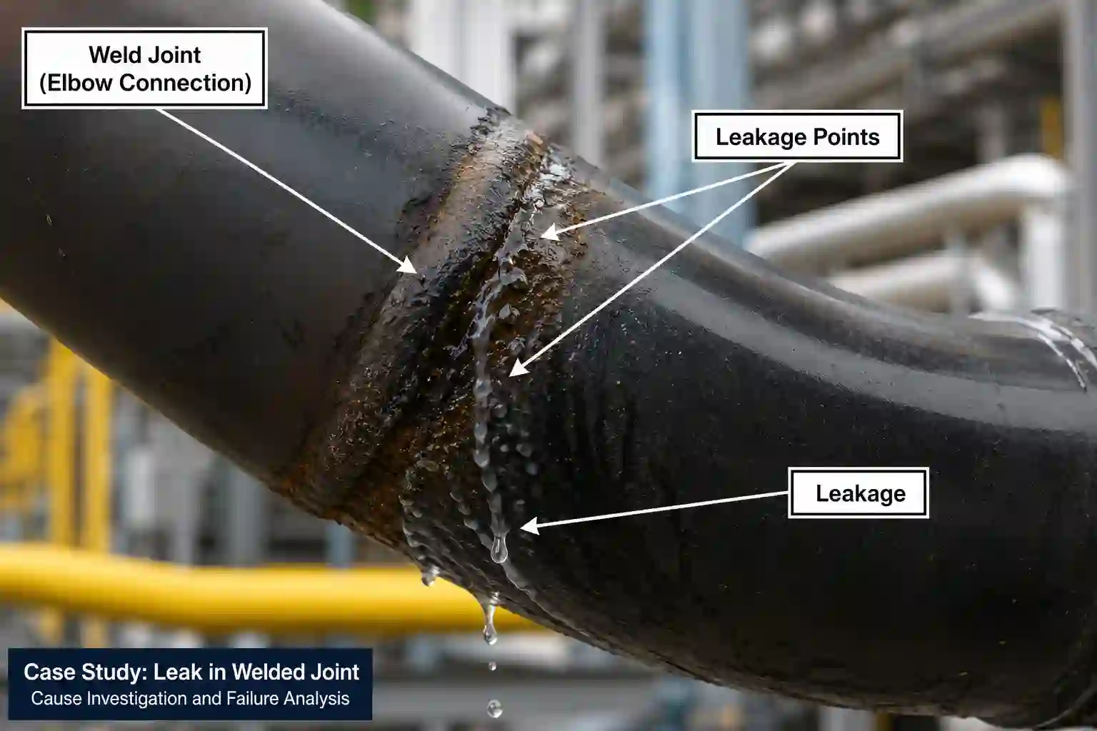
Case Study: Leak in Welded Pipe Fittings
Root Cause Analysis, Inspection Methods & Prevention Strategies
📑 Table of Contents
Ch 1: Introduction • Ch 2: Project Overview • Ch 3: Technical Specs • Ch 4: Symptoms & Detection • Ch 5: Failure Analysis • Ch 6: RCA • Ch 7: Corrective Actions • Ch 8: Preventive Actions • Ch 9: Lessons Learned • Ch 10: Conclusion📌 Chapter 1: Introduction
🔹 Importance of Sealing in Piping Systems
Piping systems serve as the vital circulatory network in oil, gas, petrochemical, power generation, and process industries. Any leakage in these systems can have catastrophic consequences. Butt-weld fittings are the most widely used type of pipe connections due to their high mechanical strength, structural integrity, and resistance to pressure and temperature. For more information on various butt-weld fittings, please visit the dedicated page.
However, even a high-quality weld can become a source of leakage if process parameters are not followed, consumables are improperly selected, or stresses exceed design limits. In this case study, we examine a leakage incident at a welded elbow connection in a steam transmission line.
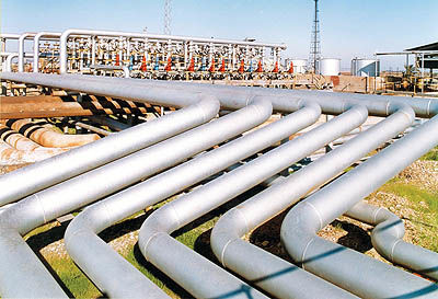
Figure 1: Overview of piping systems and welded fittings at a refinery
🔹 Costs of Leakage
Costs associated with pipeline leaks can be divided into four main categories:
| Cost Type | Description | Approximate Amount |
|---|---|---|
| Emergency Repair Costs | Labor, equipment, consumables, component replacement | 3–5× planned maintenance cost |
| Production Downtime | Cost per hour of shutdown in a refinery | Up to $2 million |
| Safety Costs | Safety equipment, training, PPE | Variable |
| Environmental Costs | Cleanup, fines, compensation | Up to millions of dollars |
📌 Key Statistic
According to industry reports, more than 40% of industrial incidents in oil and gas facilities are caused by leaks in piping systems and connections.
🔹 Safety Hazards
Leaks in piping systems can lead to:
- 🔥 Fires and explosions (with flammable fluids)
- ☠️ Release of toxic gases such as hydrogen sulfide (H₂S)
- 🔥 Thermal burns (from steam and hot fluids)
- ⚠️ Mechanical injury from high-pressure fluid impingement
🔹 Environmental Damage
Release of petroleum and chemical substances into the environment is one of the most costly and irreversible industrial damages:
- Soil and groundwater contamination
- Damage to aquatic and terrestrial ecosystems
- Expensive cleanup operations (up to tens of millions of dollars)
- Heavy fines from regulatory bodies (EPA, environmental agencies)
🔹 Production Downtime
Production downtime in process industries represents the single largest operational cost:
| Industry | Cost per Hour of Downtime |
|---|---|
| Oil Refinery | $1.5–2 million |
| Petrochemical Plant | $1–1.5 million |
| Power Plant | $500–800 thousand |
| Gas Transmission | $300–500 thousand |
🏭 Chapter 2: Project Overview (Case Study)
🔹 General Project Specifications
The project under review is a gas refinery located in the southern region of the country, responsible for natural gas processing and production of by-products. The specific unit in question is the Sulfur Recovery Unit (SRU) and its associated superheated steam transmission lines.
Figure 2: Overview of the Sulfur Recovery Unit (SRU) at the refinery
| Parameter | Value |
|---|---|
| Project Type | Gas Refinery |
| Operating Unit | Sulfur Recovery Unit (SRU) |
| Fluid | Superheated Steam |
| Design Pressure | 25 bar (362 psi) |
| Design Temperature | 220°C |
| Pipe Line | 8 inch, Schedule 40 |
🔹 Incident Description
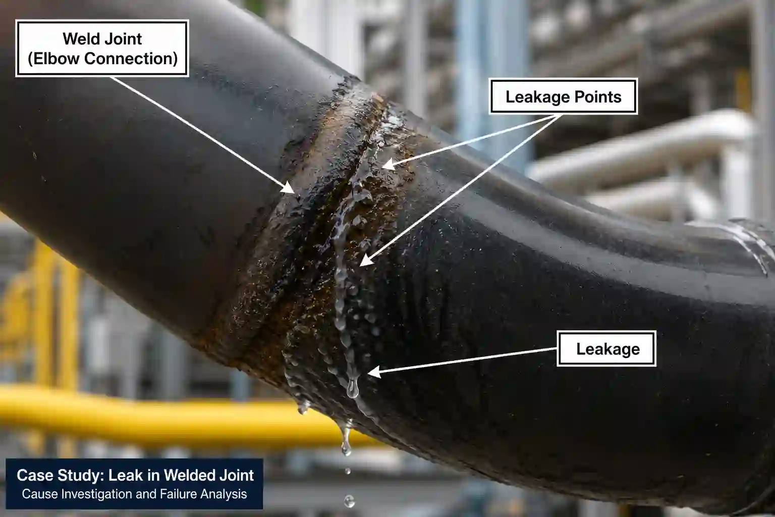
The incident occurred during the Hydrotest phase, after the completion of welding and installation. During the hydrostatic test at 1.5 times the design pressure (37.5 bar), a leak was detected at one of the 8-inch elbows in the condensate return line.
| Stage | Time |
|---|---|
| Welding Completion | Day 1 |
| Hydrotest Performed | Day 3 |
| Leak Observed | During Hydrotest |
| Operations Halted | Immediately |
Detection Method: The leak manifested as water droplets from the weld toe area on the intrados (inside radius) of the elbow. As pressure increased, the leak intensity escalated to a water spray.
📐 Chapter 3: Technical Specifications
🔹 Pipe Specifications
| Specification | Value |
|---|---|
| Standard | ASTM A106 |
| Grade | B (Carbon Steel) |
| Nominal Size (NPS) | 8 inch |
| Schedule | SCH 40 |
| OD | 219.1 mm |
| WT | 8.18 mm |
| Seamless / Welded | Seamless |
🔹 Fitting Specifications – 90° Elbow
| Specification | Value |
|---|---|
| Standard | ASME B16.9 / ASTM A234 |
| Grade | ASTM A234 WPB |
| Type | 90° Long Radius (LR) Elbow |
| Nominal Size | 8 inch |
| Schedule | SCH 40 |
| Bend Radius | 1.5D = 304.8 mm |
| Manufacturing | Seamless |
🔹 Welding Procedure (WPS)
| Parameter | Value |
|---|---|
| Welding Process | GTAW (Root) + SMAW (Fill & Cap) |
| Filler Metal (GTAW) | ER70S-2 (Ø 2.4 mm) |
| Filler Metal (SMAW) | E7018 (Ø 3.2 mm) |
| Root Gap | 2–3 mm |
| Included Angle | 60–70° |
| Preheat Temperature | 100–150°C |
| Interpass Temperature | ≤ 250°C |
| PWHT | Not Performed |
| Welder Qualification | ASME Section IX |
🔹 Operating Conditions
| Parameter | Value |
|---|---|
| Fluid | Superheated Steam |
| Operating Pressure | 25 bar (362 psi) |
| Design Pressure | 25 bar |
| Hydrotest Pressure | 37.5 bar |
| Operating Temperature | 220°C |
| Design Temperature | 260°C |
| Duty Cycle | Continuous |
🔬 Chapter 4: Initial Symptoms & Leak Detection Methods
🔹 Pre-Hydrotest Symptoms
Prior to hydrotesting, there were no visible signs of leakage or defects at the connection. The initial visual inspection (VT) after welding revealed no surface defects such as undercut, surface porosity, or cracks. However, the absence of in-process inspection and advanced NDT prior to hydrotesting was a key contributing factor.
🔹 Symptoms During Hydrotest
| Symptom | Description |
|---|---|
| 🔹 Pressure Drop | Noticeable pressure drop of ~0.5 bar on the gauge |
| 🔹 Visible Leak | Water droplets from the weld area |
| 🔹 Sound | Faint whistling sound at high pressure |
| 🔹 Vibration | Mild vibration in the pipe around the connection |
| 🔹 Corrosion | No visible corrosion present |
🔹 Leak Detection Methods
The following NDT methods were employed to precisely identify the source of the leak:
1. Visual Inspection (VT)
Result: A fine crack approximately 12 mm in length was observed at the weld toe on the intrados of the elbow.
2. Dye Penetrant Testing (PT)
Result: The crack was clearly highlighted with red dye indication. Crack depth could not be estimated.
3. Ultrasonic Testing (UT)
Result: A volumetric defect was detected in the weld area using the angle beam technique, and its exact location was determined.
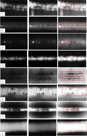
4. Radiographic Testing (RT)
Result: Radiographic images revealed a longitudinal crack in the weld area along with fine porosity in the vicinity.
5. Borescope Inspection
Result: Internal inspection revealed lack of penetration in a small portion of the weld root, which was the origin of the crack.
🔬 Chapter 5: Failure Analysis
🔹 Classification of Weld Defects Observed
Based on NDT results, the following weld defects were identified:
| # | Defect Type | Description | Location |
|---|---|---|---|
| 1 | Lack of Fusion (LOF) | Layers of weld not fused together | Fill Area |
| 2 | Lack of Penetration (LOP) | Incomplete root penetration | Root Area |
| 3 | Porosity | Trapped gas bubbles in the weld | Scattered |
| 4 | Slag Inclusion | Residual slag in the weld | Fill Area |
| 5 | Hydrogen Crack | Hydrogen-induced cracking | Weld Toe |
| 6 | Undercut | Groove at the weld edge | Weld Toe |
🔹 Metallurgical Analysis
Sampling from the weld and base metal was performed for metallurgical analysis:
1. Heat Affected Zone (HAZ)
| Parameter | Observed Value | Allowable Value |
|---|---|---|
| Hardness | HV 280–320 | ≤ HV 250 |
| Microstructure | Martensite + Bainite | Ferrite + Pearlite |
| Grain Size | Coarse Grained | Fine Grained |
⚠️ Result
High HAZ hardness was caused by rapid cooling rate, leading to the formation of brittle martensitic structure.
2. Residual Stress Analysis
Result: High residual stresses were present in the weld area due to lack of PWHT and high heat input.
🔹 Design Review & Mechanical Stress Analysis
The following design factors were evaluated:
| Factor | Evaluation Method | Result |
|---|---|---|
| Mechanical Stress | CAESAR II Analysis | Within allowable limit (ASME B31.3) |
| Pipe Support | Location & Type | Inadequate – Excessive span |
| Expansion Loop | Thermal Expansion | Not incorporated in design |
| Nozzle Load | Load Calculation | Within allowable limit |
| Alignment | Piping Alignment | 2 mm deviation (noticeable) |
📌 Key Finding
Inadequate pipe support design and the absence of thermal expansion consideration resulted in additional bending stress on the welded connection.
🧩 Chapter 6: Root Cause Analysis (RCA)
🔹 5 Whys Method
The 5 Whys method was used to identify the root cause:
❓ Why did the leak occur?
→ Due to the presence of a crack in the weld area
❓ Why did the crack form in the weld area?
→ Due to the formation of brittle martensitic structure in HAZ
❓ Why did martensitic structure form in HAZ?
→ Due to rapid cooling of the weld and lack of PWHT
❓ Why was the cooling rate rapid and PWHT not performed?
→ Due to inadequate control of welding parameters (Heat Input and Preheating)
❓ Why were the welding parameters not controlled?
→ Due to insufficient welder qualification and lack of adequate supervision
🎯 Root Cause
Insufficient welder qualification and lack of effective quality supervision led to deviation from the approved WPS, ultimately resulting in connection failure.
🔹 Fishbone (Ishikawa) Diagram
Environment Material
│ │
▼ ▼
┌──────────────────┐ ┌──────────────────┐
│ • High Wind │ │ • Material Mismatch│
│ • High Humidity │ │ • Unknown Heat No. │
└──────────────────┘ └──────────────────┘
│ │
└──────────┬───────────┘
│
▼
┌──────────────────────┐
│ 🔴 LEAK IN WELDED │
│ ELBOW CONNECTION │
└──────────────────────┘
│
┌──────────┴───────────┐
│ │
▼ ▼
┌──────────────────┐ ┌──────────────────┐
│ • Inadequate WPS │ │ • Poor Pipe │
│ • Incorrect │ │ Supports │
│ Parameters │ │ • No Expansion │
└──────────────────┘ └──────────────────┘
│ │
▼ ▼
Method Machine
🔹 Fault Tree Analysis (FTA)
┌─────────────────────────┐
│ LEAK IN WELDED ELBOW │
│ CONNECTION – 8" │
└─────────────────────────┘
│
┌──────────────┴──────────────┐
│ │
▼ ▼
┌─────────────────┐ ┌─────────────────┐
│ WELD DEFECT │ │ EXTERNAL STRESS │
└─────────────────┘ └─────────────────┘
│ │
┌──────┴──────┐ ┌───────┴───────┐
│ │ │ │
▼ ▼ ▼ ▼
┌───────┐ ┌───────┐ ┌────────────┐ ┌────────────┐
│ LOF │ │ LOP │ │ PIPE │ │ THERMAL │
│ │ │ │ │ SUPPORT │ │ EXPANSION │
└───────┘ └───────┘ └────────────┘ └────────────┘
│ │ │ │
└──────┬──────┘ └───────┬───────┘
│ │
▼ ▼
┌─────────────────┐ ┌─────────────────┐
│ INSUFFICIENT │ │ INADEQUATE │
│ WELDER QUALITY │ │ DESIGN │
└─────────────────┘ └─────────────────┘
│ │
└──────────────┬──────────────┘
│
▼
┌─────────────────────────┐
│ 🔴 ROOT CAUSE: │
│ LACK OF QUALITY CONTROL │
│ & SUPERVISION │
└─────────────────────────┘
🛠️ Chapter 7: Corrective Actions
After identifying the root cause, the following corrective actions were implemented:
🔹 1. Replacement of Defective Fitting
- Action: Cut out and replace the defective elbow with a new one of the same specification
- Supplier: Iran Etesal Asia (with EN 10204 3.1 certification)
- Result: Complete removal of the defective area
🔹 2. WPS Revision
| Parameter | Previous Value | Revised Value |
|---|---|---|
| Preheat Temperature | 100–150°C | 150–200°C |
| Interpass Temperature | ≤ 250°C | ≤ 300°C |
| Heat Input (Max) | 1.5 kJ/mm | 2.0 kJ/mm |
| PWHT | Not Performed | Required |
| PWHT Temperature | N/A | 620–660°C |
| PWHT Holding Time | N/A | 1 hour / inch |
🔹 3. Welder Team Replacement
- Previous welder was replaced due to non-compliance with project requirements
- New welder was performance-qualified under the supervision of the chief inspector
- Result: Improved weld quality in subsequent connections
🔹 4. PWHT (Post Weld Heat Treatment)
| Parameter | Value |
|---|---|
| PWHT Temperature | 650°C ± 15°C |
| Soaking Time | 2 hours |
| Heating Rate | ≤ 200°C/h |
| Cooling Rate | ≤ 250°C/h |
| Result | Reduced residual stress and HAZ hardness to HV 200–220 |
🔹 5. Pipe Support Modification
| Action | Details |
|---|---|
| Number of Supports | Increased from 3 to 5 |
| Support Type | Changed from Simple to Adjustable Spring Support |
| Support Spacing | Reduced from 6 m to 4 m |
| Result | Bending stress reduced by 30% |
🔹 6. Inspection Procedure Revision
- Increased in-process inspection frequency
- 100% NDT on all welded connections
- Documentation and recording of all welding parameters
🛡️ Chapter 8: Preventive Actions
To prevent recurrence of similar incidents, the following preventive actions were developed and implemented:
🔹 1. Heat Input Control
- Installed Heat Input monitoring devices on welding machines
- Automatic recording of welding parameters (voltage, current, travel speed)
- Alert threshold: in case of deviation from the specified range
- Result: Prevention of excessive heat input to the base metal
🔹 2. Welder Qualification
- Initial qualification test: per ASME Section IX
- Periodic re-qualification: every 6 months
- Performance monitoring: supervision during actual work
- Record keeping: complete documentation of all welder data
🔹 3. In-Process Inspection
| Stage | Inspection Method | Timing |
|---|---|---|
| Pre-Weld | VT + Material Verification | Before start |
| During Welding | VT + PT (initial layers) | Between passes |
| Post-Weld | VT + PT + MT | Immediately |
| Post-PWHT | VT + PT + MT + UT | After PWHT |
| Post-Hydrotest | VT + PT + MT | After test |
🔹 4. Material Control
- PMI (Positive Material Identification) for all consumables
- Heat Number control and documentation
- Proper storage with environmental controls
- Sourcing from certified suppliers like Iran Etesal Asia
🔹 5. Pre-Commissioning Inspection
- Hydrotest at 1.5× design pressure
- Pneumatic test (if required)
- Full NDT inspection of all critical connections
- Complete documentation of all results
📖 Chapter 9: Lessons Learned
| # | Lesson Learned | Significance |
|---|---|---|
| 1 | Importance of in-process inspection | Early defect detection reduces repair costs |
| 2 | Mandatory PWHT for carbon steel | Reduces residual stress and prevents hydrogen cracking |
| 3 | Precise Heat Input control | Prevents brittle microstructural formation in HAZ |
| 4 | Welder qualification | Direct impact on final weld quality |
| 5 | Proper pipe support design | Reduces mechanical stress on connections |
| 6 | Documentation importance | Enables future analysis and reference |
| 7 | Sourcing from reputable suppliers | Ensures material quality and traceability |
🔹 Final Checklist for Future Projects
- ✅ WPS approval before welding begins
- ✅ Welder and inspector qualification
- ✅ Material control and PMI
- ✅ Stage-by-stage inspection throughout the process
- ✅ PWHT for critical welds
- ✅ Proper pipe support design
- ✅ Hydrotest at appropriate pressure
- ✅ Complete project documentation
🎯 Chapter 10: Final Conclusion
✅ Overall Conclusion
The case study demonstrated that the leak in the welded elbow connection resulted from a combination of technical, human, and management factors:
- Technical factors: Lack of PWHT, formation of brittle martensitic structure in HAZ, high residual stress
- Human factors: Insufficient welder qualification, deviation from approved WPS
- Management factors: Inadequate supervision, lack of in-process inspection
🔹 Key Recommendations
| Recommendation | Description |
|---|---|
| 🔹 Adhere to Standards | Strict compliance with ASME B31.3, ASME Section IX, API 570 |
| 🔹 Quality Control | Implement a comprehensive QC program with in-process inspection |
| 🔹 Training | Continuous training for welders and inspectors |
| 🔹 Reputable Supplier | Partner with certified suppliers like Iran Etesal Asia |
| 🔹 Documentation | Complete recording of all project data |
💡 Final Message
"Prevention of leakage is always less expensive than repair. Investment in weld quality and inspection is the best investment to ensure safety and production continuity."
❓ Frequently Asked Questions (FAQ)
1. Why do welded fittings leak?
Leaks in welded fittings typically occur due to: weld defects (Lack of Fusion, Porosity, cracks), mechanical stress (poor support design or thermal expansion), improper welding process (high Heat Input, lack of Preheating and PWHT), and substandard consumables.
2. What is the most common cause of leakage in pipelines?
According to industry statistics, the most common cause of leakage is hydrogen-induced cracking (HIC) in the HAZ due to lack of PWHT and rapid cooling of the weld.
3. How is weld leakage detected?
Detection methods include: Visual Inspection (VT) for visible leaks, Dye Penetrant Testing (PT) for surface cracks, Ultrasonic Testing (UT) for internal defects, Radiographic Testing (RT) for volumetric defects, and Hydrotesting for pressure-based leak detection.
4. Does Hydrotest detect all leaks?
No. Hydrotest only detects active leaks at the time of testing. Subsurface defects such as fine cracks or weld defects that do not leak during hydrotest may later lead to failure during operation.
5. Does PWHT prevent cracking?
Yes. PWHT helps prevent cracking by: reducing residual stress, reducing HAZ hardness, diffusing hydrogen from the weld zone, and improving the microstructure.
6. What is the difference between Porosity and Lack of Fusion?
Porosity: Trapped gas bubbles in the weld – appears as round dark spots on RT.
Lack of Fusion: Incomplete fusion between weld layers – appears as a dark line without continuity on RT.
7. What is the best NDT method for leak detection?
The best method depends on the defect type:
Surface cracks → PT or MT
Subsurface cracks → UT (Angle Beam)
Volumetric defects (Porosity, Slag) → RT
Root defects → RT or UT
8. How can future leaks be prevented?
To prevent future leaks:
✅ Control welding parameters (Heat Input, Preheating)
✅ Perform PWHT for critical welds
✅ Implement in-process inspection
✅ Design proper pipe supports with thermal expansion consideration
✅ Source materials from reputable suppliers (Iran Etesal Asia)
🏭 Iran Etesal Asia – Your Trusted Piping Partner
Over 30 years of experience in manufacturing premium butt-weld fittings in compliance with international standards.
Contact us for consultation and price inquiries.
📚 References & Related Links
- 📄 ASME B16.9 – Butt-Weld Fittings Standard
- 🔧 Elbow Specifications
- 📐 Tee Dimensions
- 📏 Reducer Dimensions
- 🔩 Butt-Weld Fittings Overview
- 📋 Product List
- 🛒 Butt-Weld Cap
- 🛒 Butt-Weld Reducer
- 🛒 Butt-Weld Tee
- 🛒 Butt-Weld Elbow
- 🛒 Pipe Nipple
- 📄 ASME Codes & Standards
- 📄 API Standards
- 📄 ASTM International
- 📄 MSS Standards