ERW, LSAW, SSAW, and Seamless Pipe Installation Guide: Best Practices, Key Considerations, and Common Mistakes

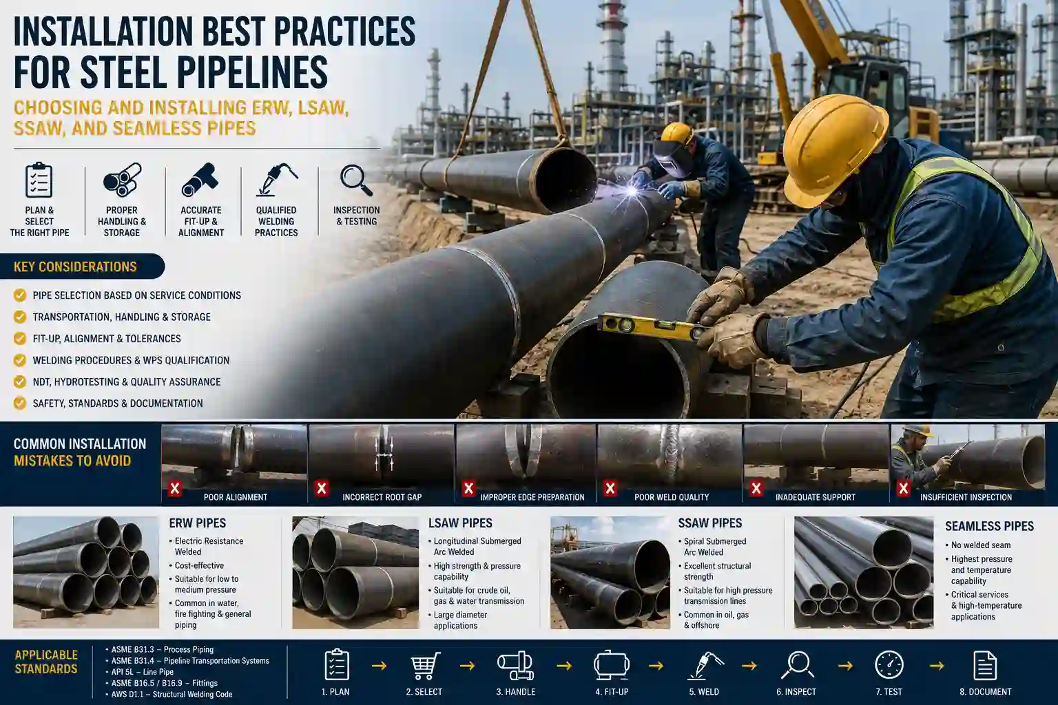
Installation Best Practices for Steel Pipelines: Choosing and Installing ERW, LSAW, SSAW, and Seamless Pipes
Table of Contents
- Introduction
- 1. Understanding Steel Pipe Manufacturing Methods
- 2. Selecting the Right Pipe Before Installation
- 3. Receiving, Inspection and Storage
- 4. Pipe Handling Best Practices
- 5. Pipe Fit-Up and Alignment
- 6. Welding Considerations
- 7. Inspection During Installation
- 8. Pressure Testing
- 9. Corrosion Protection
- 10. Installation Challenges for Different Pipe Types
- 11. Common Installation Mistakes
- 12. Safety Requirements
- 13. Inspection Checklist
Introduction
The installation of steel pipelines represents one of the most critical phases in the lifecycle of any fluid transportation system. Whether for oil, gas, water, or chemical products, the quality of pipeline installation directly determines the safety, reliability, service life, and operating costs of the entire infrastructure. Proper installation practices ensure that the pipeline performs as designed, withstanding internal pressures, external loads, and environmental conditions over decades of service.
Steel pipelines are manufactured using several distinct processes: Seamless, Electric Resistance Welded (ERW), Longitudinal Submerged Arc Welded (LSAW), and Spiral Submerged Arc Welded (SSAW). Each type has specific characteristics, advantages, and limitations that influence installation requirements. Understanding these differences is essential for engineers, contractors, and inspectors responsible for pipeline construction.
This article provides comprehensive installation best practices for all steel pipe types, based on internationally recognized standards including ASME B31.3, B31.4, B31.8, API 5L, API 1104, and ISO 3183. It covers the full installation lifecycle from receiving inspection through pressure testing, with practical guidance for avoiding common mistakes and ensuring long-term pipeline integrity.
1. Understanding Steel Pipe Manufacturing Methods
Before discussing installation practices, it is essential to understand how each pipe type is manufactured, as the manufacturing method influences handling, welding, and inspection requirements.
1.1 Seamless Pipes
Seamless pipes are manufactured from solid steel billets that are heated and pierced to form a hollow tube, then rolled or extruded to the final dimensions. The process produces pipe with no weld seam, resulting in superior strength, uniformity, and pressure containment capability. Seamless pipes are available from small diameters down to 1/8 inch up to 24 inches or larger.
- Key Advantages: Highest pressure capacity, excellent corrosion resistance due to no weld seam, uniform wall thickness, superior fatigue resistance, and no risk of seam-related defects.
- Limitations: Higher cost compared to welded pipes, limited to smaller diameters, and longer production lead times.
- Typical Applications: High-pressure oil and gas systems, power plant boilers, chemical processing, critical services where failure is not acceptable, and applications requiring superior fatigue resistance.
1.2 Electric Resistance Welded (ERW) Pipes
ERW pipes are produced by cold-forming steel coils into cylindrical shapes and welding the longitudinal seam using high-frequency electric resistance welding. This process creates a precise, cost-effective pipe with excellent dimensional accuracy. ERW pipes are typically manufactured from 1/8 inch up to 24 inches in diameter, though some mills can produce larger sizes.
- Key Advantages: Cost-effective, accurate dimensions, smooth internal surface, long lengths up to 80 feet, consistent quality, and excellent weld quality when properly manufactured.
- Limitations: Generally limited to 24-inch diameter maximum, lower pressure rating compared to seamless in some applications, historical quality concerns with pre-1970 pipe, and potential for seam-related issues if not properly manufactured.
- Typical Applications: Water and gas transmission, structural applications, low-pressure systems, oil and gas pipelines, and general industrial piping.
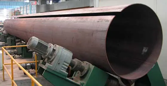
1.3 Longitudinal Submerged Arc Welded (LSAW) Pipes
LSAW pipes are manufactured by forming steel plates into cylindrical shapes and welding the longitudinal seam using submerged arc welding. The process produces high-quality welds capable of withstanding high pressures. LSAW pipes are available in large diameters from approximately 16 inches up to 60 inches or more.
- Key Advantages: Excellent weld quality, high pressure capacity, thick walls possible, recognized as the only pipe type permitted in high-risk areas under some standards, and superior quality for critical applications.
- Limitations: Higher cost than ERW, limited to 40-foot lengths (plate length limitation), and longer production times compared to ERW.
- Typical Applications: Long-distance oil and gas pipelines, high-pressure applications, offshore projects, areas requiring maximum safety, and critical transmission lines.
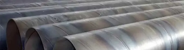
1.4 Spiral Submerged Arc Welded (SSAW) Pipes
SSAW pipes are produced by spirally forming steel coils into pipe shapes and welding the helical seam using submerged arc welding. The spiral design allows production of large diameters from narrower coils. SSAW pipes are available in large diameters from 24 inches up to 60 inches or more.
- Key Advantages: Cost-effective, flexible diameter options, fast production speeds, and ability to produce large diameters from readily available coils.
- Limitations: Longer weld length (approximately 1.3 times the pipe length), potential for weld defects, limited acceptance in some jurisdictions for mainline transmission, and more complex stress analysis.
- Typical Applications: Water transmission, low-pressure systems, piling, distribution lines in some countries, and less critical applications.
| Feature | Seamless | ERW | LSAW | SSAW |
|---|---|---|---|---|
| Manufacturing | Pierced billet, no weld | Cold-formed + electric resistance welding | Plate rolled + longitudinal SAW | Coil rolled + spiral SAW |
| Diameter Range | 1/8" – 24" | 1/8" – 24" (up to 26") | 16" – 60"+ | 24" – 60"+ |
| Pressure Capacity | Highest | High | Very High | Moderate |
| Cost | Highest | Lowest | Moderate-High | Low |
| Length | Variable | Up to 80 ft | 40 ft | Up to 80 ft |
| Typical Use | High-pressure, critical | Water, gas, structures | Oil & gas pipelines | Water, low-pressure systems |
2. Selecting the Right Pipe Before Installation
Proper pipe selection is the foundation of a successful installation. The following factors must be evaluated during the engineering phase to ensure the chosen pipe type meets all operational requirements.
2.1 Design and Operating Factors
- Pressure: High-pressure systems typically require seamless or LSAW pipes. ERW and SSAW may be suitable for lower-pressure applications. The design pressure must be carefully evaluated against the pipe's pressure rating per ASME B31.3, B31.4, or B31.8.
- Temperature: Operating temperature affects material selection and may influence the choice between seamless and welded pipes. Elevated temperatures reduce allowable stress and may require specific material grades.
- Corrosion: Seamless pipes offer superior resistance to corrosion due to the absence of a weld seam. For welded pipes, proper material selection and coating are critical. Corrosive environments may require corrosion-resistant alloys or additional protection.
- Fluid Type: Corrosive, sour, or abrasive fluids may require specific pipe materials (e.g., NACE-compliant steels for sour service). The fluid characteristics must be considered in material selection.
- Project Standards: ASME B31.4 (liquid pipelines), B31.8 (gas pipelines), and B31.3 (process piping) have different requirements. Compliance with the applicable code is mandatory.
- Cost: ERW is generally the most cost-effective option, followed by SSAW, LSAW, and seamless. Cost considerations must be balanced against performance requirements.
- Availability: Availability of specific sizes and grades may influence selection. ERW pipe above 24 inches is uncommon, and seamless pipe in large diameters may have extended lead times.
- Transportation: The availability of transportation and handling equipment for long lengths or large diameters must be considered. LSAW pipe's 40-foot length may require more joints per mile.
2.2 Selection Guidelines by Application
- High-Pressure Gas Transmission: LSAW or seamless pipes are typically preferred for Class 1 and 2 areas. These types provide the highest level of safety and reliability for critical gas transmission.
- Liquid Pipelines: ERW pipe is commonly used for diameters up to 24 inches; larger lines use LSAW or SSAW. The selection depends on pressure, terrain, and environmental factors.
- Water Transmission: ERW or SSAW pipes provide cost-effective solutions for water transmission lines where pressures are typically lower.
- Structural Applications: ERW pipe is widely used due to its dimensional accuracy and cost-effectiveness for piling, structural supports, and other non-pressure applications.
- Offshore/Deepwater: LSAW or seamless pipes are typically required for offshore applications due to the severe conditions and high consequences of failure.
3. Receiving, Inspection and Storage
Proper receiving inspection and storage are critical to maintaining pipe integrity before installation. The pipeline should be handled and stored to prevent damage to the pipe body, ends, and coatings.
3.1 Receiving Inspection
- Visual Inspection: Check for visible damage, dents, gouges, or deformation. Ensure the pipe is straight and free from defects. Any damage must be documented and reported.
- Material Verification: Confirm the pipe matches the purchase order and project specifications. Verify the size, grade, schedule, and wall thickness against the order.
- Mill Certificates: Review the manufacturer's mill test reports (MTRs) to verify material grade, chemical composition, and mechanical properties meet the applicable standard (e.g., API 5L). Ensure the MTRs are complete and traceable.
- Pipe Markings: Verify that the pipe is properly marked with the manufacturer, size, grade, heat number, and other required information per the applicable standard.
- Coating Inspection: Check that coatings (e.g., FBE, 3LPE, 3LPP) are intact and free from damage. Any coating damage must be repaired before installation.
- End Protection: Verify that pipe ends are protected with plastic caps or other approved methods to prevent damage and contamination.
3.2 Storage Best Practices
- Pipe Stacking: Store pipes on racks or sleepers at least 4 inches above ground to prevent moisture contact. Ensure the storage area is well-drained.
- Stacking Height: Limit stacking height to prevent deformation. A general guideline is to limit stack height to 5–6 layers depending on diameter.
- Grade Protection: When stacking, use wooden strips or other protective materials between layers to prevent coating damage and contamination.
- End Caps: Keep protective caps on pipe ends to prevent debris and moisture ingress. Replace caps if they become damaged.
- Coating Protection: Shield stored pipes from direct sunlight and UV exposure to prevent coating degradation. Use tarps or covers as necessary.
4. Pipe Handling Best Practices
Improper handling is a leading cause of pipe damage during construction. All handling operations must be conducted with care to protect the pipe and its coating from damage.
4.1 Lifting Methods
- Slings: Use fabric or synthetic slings with adequate load capacity. Avoid wire ropes or chains that can damage the coating.
- Lifting Spreaders: Use spreader bars to prevent pipe bending and stress concentration during lifting operations.
- Cranes and Forklifts: Ensure equipment has sufficient capacity and is operated by qualified personnel. Perform daily inspections of lifting equipment.
- Preventing Coating Damage: Use padding or protective material at all contact points between slings and pipe coating. Never allow chains or wire ropes to contact coated pipe directly.
- Large Diameter Pipes: Use specialized lifting equipment and ensure proper load distribution to prevent ovalization and pipe deformation.
4.2 Stringing
Stringing is the process of placing pipe sections along the pipeline route. Key considerations include:
- Route Planning: Place pipes in a sequence that matches the welding schedule to minimize handling.
- Protection: Place pipes on wooden sleepers or dunnage to keep them off the ground and protect the coating.
- Environmental Protection: Avoid placing pipes in areas prone to flooding, contamination, or damage from construction traffic.
- Safety: Ensure stringing operations do not obstruct access routes or create hazards for personnel and equipment.
5. Pipe Fit-Up and Alignment
Proper fit-up and alignment are essential for achieving quality welds and maintaining pipeline integrity. Fit-up is the process of aligning and preparing pipe ends for welding.
5.1 Key Fit-Up Parameters
- Alignment: The pipe ends must be aligned to within the tolerances specified by the welding procedure. Misalignment causes stress concentration and weld defects.
- Ovality: Pipes must be round; excessive ovality can cause fit-up problems. Check for ovality and correct using line-up clamps or mechanical expanders.
- Root Gap: The gap between pipe ends must be uniform and within the range specified in the Welding Procedure Specification (WPS). For API 1104 welding, root gap is typically 1/16" to 1/8" depending on the procedure.
- High-Low Mismatch: Internal and external high-low mismatch must be minimized. For API 1104, the internal mismatch should not exceed 1/8 inch.
- End Preparation: Bevels must be prepared to the angle and root face specified in the WPS. The standard bevel angle is typically 37.5° ± 2.5°.
- Bevel Inspection: Verify bevel dimensions and surface condition before welding. The bevel must be clean and free from defects.
- Tack Welding: Apply sufficient tacks to hold alignment. Tack welds must be properly cleaned and integrated into the final weld. For pipeline welding under API 1104, tack welds must be made by qualified welders.
- Pipe Supports: Use internal or external line-up clamps to maintain alignment during welding. Ensure supports do not create additional stress.
6. Welding Considerations
Welding is the most critical operation in pipeline installation. Proper welding procedures and qualified personnel are essential for weld quality and long-term pipeline integrity.
6.1 Welding Documentation
- WPS (Welding Procedure Specification): A qualified procedure must be used for all welding. The WPS defines the welding parameters, joint design, preheat, and other critical variables.
- PQR (Procedure Qualification Record): Provides documented evidence that the WPS produces acceptable welds. PQRs must be qualified per API 1104 or ASME Section IX.
- Welder Qualification: All welders must be qualified for the specific process, material, position, and joint design. Qualification must be verified before welding begins.
6.2 Welding Parameters
- Preheating: Required when the material has a carbon equivalent (CE) exceeding 0.32% per B31.4. Preheat temperature must be specified in the WPS and monitored during welding.
- Interpass Temperature: Must be controlled to avoid excessive grain growth and hydrogen cracking. The maximum interpass temperature is typically specified in the WPS.
- Heat Input: Excessive heat input can degrade material properties. Heat input must be calculated and controlled per the WPS to maintain mechanical properties.
- Multi-Pass Welding: Most pipeline welds are multi-pass. Each pass must be cleaned and inspected before the next pass to ensure defect-free welds.
- Root Pass: Must achieve full penetration. For API 1104, the root pass should be made with a cellulosic electrode (e.g., E6010 or E7010) for pipeline applications.
- Fill Passes: Fill passes must achieve complete fusion and uniform weld build-up. Proper sequence and technique are essential.
- Cap Pass: The final pass must provide a smooth, slightly convex profile with proper reinforcement. Cap passes should be free from undercut and excessive reinforcement.
6.3 Welding Differences by Pipe Type
- ERW Pipe: The seam weld is already present from manufacturing. Welding of ERW joints is similar to other pipe types, but care should be taken at the seam area to ensure proper fusion.
- LSAW and SSAW Pipe: The weld seam must be considered when orienting the pipe for welding. The seam should be positioned to avoid conflict with other weld joints.
- Seamless Pipe: No seam to consider. Welding procedures may be slightly less complex, but all other requirements remain the same.
- Dissimilar Material Welding: When welding pipe of different material grades (e.g., API 5L X42 to ASTM A106), the welding procedure must be qualified for the S-Number groups involved. Both materials are typically S-1, Group 1, and a PQR for P-1 material qualifies for S-1 materials.
7. Inspection During Installation
Inspection during installation ensures that all welding and construction activities meet the required quality standards. A comprehensive inspection program is essential for pipeline integrity.
| Inspection Method | Description | Defects Detected |
|---|---|---|
| Visual Inspection (VT) | Non-destructive surface inspection of all accessible surfaces | Surface cracks, undercut, porosity, poor profile, dimensional issues |
| Penetrant Testing (PT) | Dye penetrant inspection for surface-breaking defects | Surface cracks, porosities, laps, and other surface discontinuities |
| Magnetic Particle (MT) | Detects surface and near-surface discontinuities in ferromagnetic materials | Surface and sub-surface cracks, inclusions, and other defects |
| Radiographic Testing (RT) | X-ray or gamma-ray inspection of weld internal structure | Porosity, slag, lack of penetration, internal cracks, and inclusions |
| Ultrasonic Testing (UT) | High-frequency sound waves to detect internal flaws | Lack of fusion, cracks, laminations, and thickness measurements |
| Dimensional Verification | Check as-built dimensions against design drawings | Misalignment, incorrect dimension, ovality issues |
For pipeline welding, inspection must follow the requirements of API 1104. This includes acceptance criteria for weld defects and requirements for repair welding. All NDT must be performed by qualified personnel using calibrated equipment.
8. Pressure Testing
Pressure testing is the final verification of pipeline integrity before commissioning. All pipelines must be tested per the applicable code requirements to ensure safety and reliability.
8.1 Hydrostatic Testing
- Purpose: Validates pipeline integrity and leak tightness. Hydrostatic testing is the preferred method for most pipelines.
- Test Pressure: Generally at least 1.25 times the design pressure for B31.4 and B31.8 pipelines. The test pressure must be maintained for the specified duration.
- Test Duration: As specified by the code and project requirements, typically 2 to 24 hours depending on the pipeline length and class.
- Water Quality: Test water must be clean, low-chloride, and suitable for the pipe material to prevent corrosion or contamination.
- Safety: Personnel must be cleared from the test area during pressurization. Safety barriers and warning signs must be in place.
8.2 Pneumatic Testing
- When Used: Generally limited to low-pressure systems or where water is not feasible. Pneumatic testing is more dangerous and requires additional precautions.
- Safety: Pneumatic testing carries higher risk than hydrostatic testing and requires additional safety precautions, including pressure relief valves and blast zones.
- Test Pressure: Typically lower than hydrostatic test pressure, often 1.1 times the design pressure.
8.3 Test Documentation
- Test Records: Document test pressure, duration, and results. Records must be maintained for the life of the pipeline.
- Leak Reports: Record any leaks and repair details. All leaks must be repaired and retested.
- Approval: Obtain sign-off from the client or authorized inspector before commissioning.
9. Corrosion Protection
Corrosion is the primary threat to long-term pipeline integrity. A comprehensive corrosion protection system must be installed and maintained throughout the pipeline's service life.
9.1 Coatings
- Fusion Bonded Epoxy (FBE): A thin, epoxy-based coating applied to heated pipe. Provides excellent adhesion and corrosion resistance for most environments.
- Three-Layer Polyethylene/ Polypropylene (3LPE/3LPP): Multi-layer coating system providing mechanical protection and corrosion resistance. Commonly used for extreme environments and offshore applications.
- Coal Tar Enamel: Traditional coating now largely replaced by newer technologies due to environmental concerns.
- Holiday Testing: Electrical inspection to detect pinholes or holidays in the coating. All pipelines must be holiday-tested after coating to ensure full coverage.
9.2 Cathodic Protection
- Purpose: Provides electrochemical protection to the pipe by making it a cathode in an electrochemical circuit, preventing corrosion.
- Sacrificial Anodes: Used for smaller pipelines or where external power is unavailable. Anodes are consumed to protect the pipe.
- Impressed Current: Used for larger pipelines requiring more protection. External power is applied to drive the protection current.
- Monitoring: Cathodic protection systems must be monitored regularly to ensure effectiveness and adjust as needed.
9.3 Field Joint Coating
- Girth Weld Areas: The most vulnerable area for corrosion; field joints must be coated immediately after weld inspection.
- Methods: Liquid epoxy, heat-shrink sleeves, or other approved systems suitable for the pipe coating.
- Inspection: Field joints must be inspected to ensure proper application and coverage. Holiday testing is typically required.
10. Installation Challenges for Different Pipe Types
Each pipe type presents unique installation challenges that must be addressed during planning and execution. Understanding these challenges helps in developing effective installation strategies.
10.1 ERW Pipe Installation
- Handling: More susceptible to weld seam damage; handle with care and avoid impact to the seam area.
- Welding: The weld seam must be properly oriented during fit-up. The seam should be positioned to minimize stress during welding.
- Pressure Testing: Some standards limit the maximum test pressure for ERW pipe to 95% of that for seamless pipe. Verify code requirements.
- Restrictions: Not recommended for HDD or bridge installations; avoid in compressor stations where possible.
10.2 LSAW Pipe Installation
- Handling: Limited to 40-foot lengths; more joints per mile, increasing welding requirements and inspection needs.
- Welding: Longitudinal seam must be positioned to avoid conflict with girth welds. Careful planning is required.
- Thick Walls: May require preheat and post-weld heat treatment. Thick wall welding requires more time and careful procedure control.
10.3 SSAW Pipe Installation
- Geometry: More prone to ovality and dimensional variation; careful checking is required before welding.
- Weld Length: Longer weld length than LSAW; more welding time required for each joint.
- Stress Orientation: Helical seam has different stress characteristics; engineering evaluation may be required for critical applications.
- Restrictions: Some standards limit SSAW to specific area classifications (e.g., Class 3 and 4 areas). Verify code compliance.
10.4 Seamless Pipe Installation
- Handling: No weld seam to consider; generally easier handling and less risk of seam damage.
- Cost: More expensive; typically used only where required by pressure, temperature, or service conditions.
- Advantages: Highest pressure rating; no seam-related restrictions. Ideal for critical applications.
11. Common Installation Mistakes
Understanding and avoiding common installation mistakes is essential for successful pipeline projects. The following are the most frequent errors encountered during pipeline construction.
11.1 Poor Alignment
- Consequence: Stress concentration, weld defects, fatigue cracking, and potential service failure.
- Prevention: Use line-up clamps and verify alignment before and during welding. Regular inspection ensures alignment is maintained.
11.2 Incorrect Root Gap
- Consequence: Lack of penetration or burn-through, leading to weld defects and potential leaks.
- Prevention: Use welding gauges to verify root gap. Check gap at multiple points around the circumference.
11.3 Damaged Bevels
- Consequence: Contamination and poor fusion, creating weld defects and reducing joint strength.
- Prevention: Protect bevels with caps; repair damage before welding. Inspect bevels before each weld.
11.4 Improper Lifting
- Consequence: Pipe damage, coating failure, personnel injury, and potential pipe deformation.
- Prevention: Use proper slings and padding; ensure equipment is rated for the load. Follow lifting plans.
11.5 Wrong Welding Procedure
- Consequence: Weld defects, reduced joint strength, and potential failure.
- Prevention: Always use qualified WPS; verify welder qualification. Review procedures before each shift.
11.6 Lack of Inspection
- Consequence: Undetected defects leading to in-service failure and costly repairs.
- Prevention: Follow the inspection plan; use qualified NDT personnel. Document all inspections.
11.7 Incorrect Hydrotesting
- Consequence: Over-pressure damage or inability to detect leaks. Potential for pipe failure during test.
- Prevention: Follow code requirements and test procedure. Verify test pressure and duration.
11.8 Poor Storage
- Consequence: Pipe damage, corrosion, coating loss, and contamination.
- Prevention: Store on sleepers with proper support; protect coating. Keep storage area clean and organized.
11.9 Coating Damage
- Consequence: Corrosion risk, reduced service life, and potential pipeline failure.
- Prevention: Handle carefully; repair damage immediately. Use protective materials during handling.
11.10 Documentation Errors
- Consequence: Traceability loss, regulatory issues, and inability to verify compliance.
- Prevention: Maintain complete records; use document control procedures. Review documentation regularly.
12. Safety Requirements
Pipeline installation is a high-hazard activity that requires strict adherence to safety protocols. Safety must be the top priority for all personnel involved in the project.
- PPE: Hard hats, safety glasses, steel-toe boots, gloves, and high-visibility clothing are mandatory for all personnel.
- Confined Spaces: If entering pipe or trench, use confined space entry procedures and gas monitoring. Ensure proper ventilation.
- Hot Work Permits: Required for all welding and grinding. Include fire watch and fire extinguishing equipment. Maintain permits for the duration of work.
- Lifting Safety: Use rated lifting equipment. Inspect slings, chains, and lifting gear before use. Maintain clear zones under suspended loads.
- Welding Safety: Use proper ventilation. Protect against arc flash. Keep flammables away from the work area. Use welding curtains when necessary.
- Pressure Testing Safety: Clear all personnel from the test area during pressure testing. Use safety barriers. Designate a test safety officer.
13. Inspection Checklist
Pre-Installation Checks
- ☐ Pipe material matches specifications (size, grade, schedule)
- ☐ Mill certificates (MTRs) reviewed and filed
- ☐ Pipe markings verified (heat number, grade, manufacturer)
- ☐ Visual inspection: no damage, dents, or corrosion
- ☐ Bevels properly prepared (angle, root face, cleanliness)
- ☐ Coating intact (if applicable)
- ☐ End protection in place
During Installation Checks
- ☐ Fit-up: alignment, root gap, high-low mismatch within tolerances
- ☐ Welding: WPS and welder qualification verified
- ☐ Preheat temperature (if required) verified
- ☐ Interpass temperature controlled
- ☐ NDT (RT/UT/MT/PT) performed per requirements
- ☐ Field joint coating applied and inspected
Post-Installation Checks
- ☐ Hydrostatic pressure test performed and documented
- ☐ Test pressure and duration verified
- ☐ No leaks detected
- ☐ Final inspection completed
- ☐ All documentation reviewed and filed