
Butt Weld vs Socket Weld Fittings: Which Is Better for High-Pressure Piping Systems?

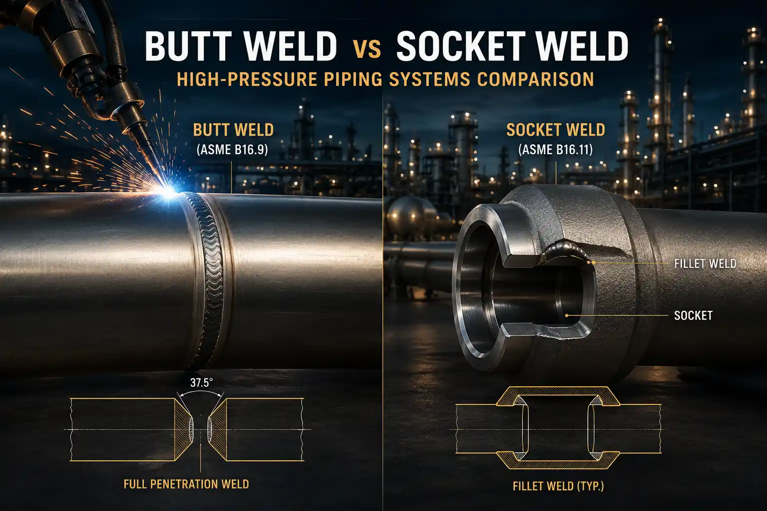
Butt Weld vs Socket Weld Fittings:
The Complete Engineering Guide for High-Pressure Piping Systems
1. Introduction
The selection of the appropriate pipe fitting connection method is one of the most fundamental yet consequential decisions in the design and construction of industrial piping systems. The choice between butt weld and socket weld fittings affects not only the initial capital expenditure but also the long-term reliability, safety, maintenance requirements, and overall lifecycle cost of the installation. In high-pressure applications, where the consequences of failure can be catastrophic, this decision becomes even more critical. This engineering guide is written for experienced engineers, EPC contractors, and plant operators who require a detailed technical understanding of these two widely used connection methods, including their advantages, limitations, inspection requirements, and correct application.
The first step in any piping project is to define the operating conditions, including design pressure, temperature, fluid properties, and environmental factors. These parameters determine the required mechanical properties of the fittings and the strength of the welded joint. Butt weld fittings, governed by ASME B16.9, provide a full-penetration weld joint that offers a smooth internal bore and a connection that is at least as strong as the pipe itself. Socket weld fittings, governed by ASME B16.11, use a fillet weld around the outside of a socket connection and are generally limited to smaller pipe sizes and less severe service conditions.
This guide provides a comprehensive, side-by-side engineering comparison of these two essential connection technologies. We will cover the fundamental principles of design, manufacturing methods, applicable codes and standards, stress distribution, flow characteristics, corrosion resistance, welding procedures, non-destructive testing, and common failure mechanisms. The objective is not to declare one technology superior to the other, but rather to equip the engineer with the technical knowledge required to make an informed selection based on the specific requirements of each application. After reading this guide, the reader will have a clear understanding of when to specify a butt weld fitting and when a socket weld fitting is the more appropriate engineering solution.
The following sections are structured to first define each fitting type, then systematically compare them across all relevant engineering parameters. We will begin by examining the fundamental characteristics of butt weld fittings, including their manufacturing, geometry, and performance. This will be followed by a similar treatment for socket weld fittings. The subsequent sections will then compare the two directly, discussing stress, flow, corrosion, welding, inspection, and cost. The final sections provide practical guidance on selection, common mistakes, and a comprehensive set of references and FAQs.
The comparison is based on established engineering standards and codes, primarily ASME B16.9, ASME B16.11, and ASME B31.3. These codes provide the legal and technical framework for the design, materials, fabrication, and inspection of piping systems. Adherence to these codes is not only a matter of good engineering practice but also a legal requirement in most jurisdictions. Therefore, the reader is strongly advised to consult the current editions of these standards when making final engineering decisions. This guide is intended as a companion to those codes, providing the underlying engineering rationale and practical insights that are not always evident from the code text alone.
2. What Are Butt Weld Fittings?
Butt weld fittings are components used to change the direction, diameter, or branching of a piping system, and are joined to the pipe by a full penetration, groove weld. In this type of connection, the ends of both the pipe and the fitting are beveled, typically to a 37.5° angle with a root face of approximately 1.6 mm, to create a V-shaped groove that allows the welder to completely fuse the weld metal through the full thickness of the pipe wall. The complete fusion ensures that the resulting joint has a smooth internal surface and a strength that is at least equal to that of the pipe itself. The primary standard governing the dimensions and tolerances of butt weld fittings is ASME B16.9, which covers sizes from NPS ½ to NPS 48.
The production of butt weld fittings typically involves the hot forming of steel plates or seamless pipes. The material is heated to a precise temperature and then shaped using dies and presses to achieve the desired geometry. This is followed by a controlled cooling process and, depending on the material grade, a post-forming heat treatment to relieve residual stresses and optimize the microstructure. The result is a fitting with uniform wall thickness, excellent mechanical properties, and a smooth internal surface that is free from crevices. This is particularly important in applications where the flowing fluid is corrosive or where solid particles are present, as a smooth surface minimizes erosion and the potential for localized corrosion.
Butt weld fittings are available in a wide variety of types, including 90 degree elbows, tees, reducers, and caps. They are manufactured from a range of materials, including carbon steel (ASTM A234), stainless steel (ASTM A403), and alloy steel. Due to their superior strength, fatigue resistance, and integrity, they are the preferred choice for high-pressure and high-temperature applications in the oil and gas, petrochemical, power generation, and refining industries. For more information on specific dimensions and weights, engineers can refer to the elbow dimensions and tee dimensions tables.
One of the key engineering advantages of butt weld fittings is the elimination of the internal crevice. In any piping system, crevices can trap stagnant fluid, leading to localized corrosion. By providing a smooth, continuous internal surface, butt weld fittings eliminate this risk. This is a particularly important consideration in services where the fluid is corrosive, such as seawater or sour crude oil. The smooth internal surface also reduces the pressure drop across the fitting, which is a significant factor in high-flow systems. The ability to achieve a full penetration weld is also critical from a structural standpoint. The weld is not simply a seal; it is an integral part of the load-bearing structure of the pipe. The butt weld is designed to transfer the full hoop and axial stresses from the pipe to the fitting, a capability that socket weld fittings cannot match.
In practice, butt weld fittings are used in a wide range of applications, from small-bore instrument lines to large-diameter main process lines. Their versatility, combined with their superior mechanical properties, makes them the default choice for most critical piping systems. The decision to use a butt weld fitting is often dictated by the pressure class of the system, the temperature, and the need for radiographic inspection. Many plant specifications require butt weld fittings for all piping above a certain size or for all lines that are subjected to cyclic or high-temperature service.
3. What Are Socket Weld Fittings?
Socket weld fittings are forged components that provide a connection by inserting the pipe into a recessed socket and then securing the joint with a fillet weld applied around the outside of the fitting. The pipe is inserted to the bottom of the socket and then withdrawn by approximately 1.6 mm (1/16 inch) to provide an expansion gap that accommodates thermal expansion and contraction, preventing the development of excessive stress at the weld root. The design and dimensions of socket weld fittings are defined in ASME B16.11, which covers sizes up to NPS 4 and includes pressure classes 3000, 6000, and 9000.
The manufacturing process for socket weld fittings differs significantly from that for butt weld fittings. They are produced by forging a solid block of steel (or other alloy) into a shape that approximates the final geometry, followed by machining of the socket and other critical dimensions. Forging produces a fine-grained, dense microstructure with excellent toughness and strength. This makes socket weld fittings a robust solution for small-bore, high-pressure systems where the material is subjected to a combination of internal pressure and external mechanical loading.
Despite their strength, socket weld fittings have certain inherent design limitations. The internal gap at the bottom of the socket creates a crevice that can trap stagnant fluid, leading to localized corrosion. The fillet weld geometry also introduces a sharp notch at the toe of the weld, which acts as a stress concentration point. Under cyclic loading, this notch can be a site for fatigue crack initiation and propagation. For this reason, many piping codes restrict the use of socket weld fittings to NPS 2 and below, especially in services subject to cyclic or thermal fatigue. Nevertheless, for instrument lines, small-bore drain and vent systems, and other non-critical applications, socket weld fittings offer a cost-effective and reliable solution.
The simplicity of the socket weld joint is one of its main attractions. Unlike a butt weld, which requires precise beveling and fit-up, a socket weld only requires a square cut on the pipe end. The pipe is simply inserted into the socket, and the fillet weld is applied. This simplicity translates into faster installation and lower labor costs. The welding procedure itself is simpler, often requiring only a single pass. This makes socket weld fittings particularly attractive for small-bore systems where the cost of a butt weld would be disproportionately high. For example, in a typical instrument air system with many small connections, the use of socket weld fittings can significantly reduce the overall project cost and schedule.
In the context of pressure piping design, socket weld fittings are often specified for Class 3000 and Class 6000 services, which are common in high-pressure gas and liquid systems. However, the engineer must carefully evaluate the service conditions. If the system is subject to severe cyclic loading, such as frequent pressure or temperature cycles, a socket weld is likely to be a poor choice. In such cases, the stress concentration at the weld toe will lead to fatigue failure. The engineer must also consider the risk of crevice corrosion. If the fluid is corrosive, the internal gap can initiate attack that could lead to leakage. In many cases, the decision to use a socket weld is dictated by space constraints. In a confined area, a socket weld may be the only practical solution.
4. Manufacturing Methods
The manufacturing methods used for butt weld and socket weld fittings are distinct, reflecting the different geometries and performance requirements of each type. Butt weld fittings are generally produced from rolled steel plate or seamless pipe through a series of hot forming and finishing operations. The process begins with cutting a piece of material to the required size, followed by heating to a temperature that renders the steel plastic enough to be formed by pressing or forging. For elbows, the material is placed over a mandrel and forced through a die to create the radius; for tees, a branch is extruded from a heated pipe section. After forming, the fitting is normalized or annealed to relieve residual stresses and to achieve the desired mechanical properties. In most cases, no machining is required, as the dimensional tolerances specified by ASME B16.9 are achieved directly by the forming process. However, special fittings or those requiring precise surface finish may be machined after heat treatment.
Socket weld fittings are manufactured using an entirely different approach. They are forged from solid bar stock or billet material. The forging process involves heating the material to a high temperature and then applying compressive force in a press or hammer to shape the material. This process aligns the grain flow of the metal to follow the contours of the fitting, resulting in superior mechanical properties and resistance to fatigue. After forging, the fittings are machined to create the socket, the inside diameter, and the end connections. Heat treatment, such as normalizing, quenching, and tempering, is performed to achieve the required strength and hardness. The entire process is tightly controlled to ensure compliance with the requirements of ASME B16.11.
Both types of fittings undergo rigorous quality control and non-destructive testing (NDT) to verify material integrity, dimensional accuracy, and the absence of internal defects. Common inspection methods include visual inspection, dimensional measurement, and ultrasonic testing. The level of inspection depends on the application, with critical systems often requiring 100% examination of the finished product. Many manufacturers, such as Iran Etesal Asia, also employ positive material identification (PMI) to ensure the alloy composition is correct, followed by hydrostatic testing to validate the pressure integrity of the finished component.
The hot forming process used for butt weld fittings is a highly specialized operation that requires careful control of temperature and deformation. If the temperature is too low, the material can crack; if it is too high, the grain structure can coarsen, leading to reduced toughness. The use of induction heating and programmable presses has greatly improved the consistency and quality of hot-formed fittings. For socket weld fittings, the forging process is equally critical. The forging temperature, the rate of deformation, and the cooling rate all affect the final microstructure. The use of close-tolerance dies and precision machining ensures that the socket is concentric and that the wall thickness is uniform.
The choice of manufacturing method has a significant impact on the cost and lead time of the fittings. Hot forming is a relatively fast process for large volumes, but the tooling costs can be high. Forging is more expensive per part but is often the only practical method for small-diameter, high-pressure fittings. The engineer should be aware of these differences when specifying fittings, as they can affect both the project cost and the delivery schedule. In many cases, standard fittings can be delivered from stock, while special sizes or materials may require a longer lead time.
5. Applicable Standards
The design, manufacture, testing, and use of butt weld and socket weld fittings are governed by a comprehensive framework of international standards. The primary standard for butt weld fittings is ASME B16.9, which covers dimensions, tolerances, marking, and material requirements for wrought butt-welding fittings. For socket weld and threaded fittings, the governing standard is ASME B16.11. These two standards are often used in conjunction with ASME B31.3 (Process Piping) and ASME Section IX (Welding and Brazing Qualifications) to ensure the integrity of the entire piping system.
Material specifications are also critical. The most commonly used material standard for butt weld fittings in carbon steel is ASTM A234, which covers the chemical and mechanical properties of wrought carbon steel and alloy steel fittings. For stainless steel butt weld fittings, the relevant standard is ASTM A403. For socket weld fittings, which are forged, the material standards are ASTM A105 (carbon steel), ASTM A182 (alloy and stainless steel), and ASTM A350 (low-temperature carbon steel). In addition, MSS SP-43 provides dimensions for stainless steel butt weld fittings, while MSS SP-75 covers high-strength butt weld fittings for large-diameter pipe.
The table below summarizes the key standards and their scope.
| Standard | Scope | Size Range |
|---|---|---|
| ASME B16.9 | Dimensions & tolerances for wrought butt-welding fittings | NPS ½ – 48 |
| ASME B16.11 | Dimensions & tolerances for forged socket-welding & threaded fittings | NPS ⅛ – 4 |
| ASME B31.3 | Process piping design and construction | All |
| ASME Section IX | Welding and brazing qualification | All |
| ASTM A234 | Wrought carbon steel & alloy steel butt weld fittings | All |
| ASTM A403 | Wrought stainless steel butt weld fittings | All |
| ASTM A420 | Wrought carbon steel & alloy steel fittings for low-temperature service | All |
| ASTM A105 | Forged carbon steel fittings (socket weld) | NPS ⅛ – 4 |
| ASTM A182 | Forged alloy & stainless steel fittings (socket weld) | NPS ⅛ – 4 |
| MSS SP-43 | Stainless steel butt-welding fittings (light wall) | NPS ½ – 24 |
| MSS SP-75 | High-strength butt-welding fittings for large diameters | NPS 2 – 48 |
| ASME B16.25 | Buttwelding ends preparation | All |
| ISO 15614 | Welding procedure qualification | All |
The engineer must also be familiar with the relevant sections of ASME B31.3, particularly Chapter VI, which covers the inspection and testing of piping systems. This code specifies the minimum requirements for NDT and hydrostatic testing. For the welding itself, ASME Section IX provides the rules for qualifying welding procedures and welders. The use of these codes is not optional in most jurisdictions. They are the legal standard of care for the design and construction of pressure piping.
6. Pressure Capability
The pressure rating of a piping connection is one of the most critical parameters in the design of high-pressure systems. For butt weld fittings, the pressure rating is determined by the thickness of the wall (schedule) of the pipe to which they are attached, as the weld joint is designed to be as strong as the pipe itself. Therefore, the maximum allowable working pressure for a butt weld fitting is calculated using the same ASME B31.3 formulas as for the pipe, using the wall thickness of the fitting and the allowable stress of the material at the design temperature. This means that a butt weld fitting installed in a Sch 80 pipe will have the same pressure rating as the Sch 80 pipe, provided that the fitting is manufactured to ASME B16.9 and the weld joint is free from defects.
Socket weld fittings, on the other hand, are assigned pressure classes rather than being directly tied to a pipe schedule. ASME B16.11 defines three classes: Class 3000, Class 6000, and Class 9000. These classes correspond to specific schedules of pipe with which they are typically used. For example, Class 3000 socket weld fittings are usually used with Sch 80 pipe, Class 6000 with Sch 160 pipe, and Class 9000 with XXS pipe. The pressure-temperature ratings for these classes are provided in ASME B16.11 and are based on the material grade and the allowable stress at the design temperature. It is important to note that the pressure rating of a socket weld joint is limited by the strength of the fillet weld, which is generally lower than the strength of the full-penetration butt weld.
The effect of temperature on pressure rating is another crucial consideration. For both types of fittings, the allowable stress of the material decreases as the temperature increases, which means that the maximum allowable working pressure also decreases. However, because butt weld fittings are integrated with the pipe wall, they maintain a higher pressure capacity at elevated temperatures compared to socket weld fittings of the same nominal size. For high-temperature services, such as superheated steam or high-temperature hydrocarbon lines, butt weld fittings are almost always the preferred choice.
In practice, the engineer must always consult the pressure-temperature tables in ASME B31.3 and ASME B16.11 to determine the correct rating for a given application. The operating conditions must be compared to the rating of the fitting to ensure a factor of safety. The engineer must also account for any transient conditions, such as pressure spikes during start-up or shutdown, which could exceed the steady-state rating. The use of a higher class fitting than the minimum required is a common practice to provide a margin of safety and to allow for future changes in operating conditions.
Another important consideration is the use of fittings in cyclic service. The repeated pressurization and depressurization of a system can cause fatigue failure, particularly at stress concentrations. The butt weld joint, with its low stress concentration factor, is well suited to such service. The socket weld joint, with its high stress concentration, is not. In many cyclic services, the use of socket weld fittings is prohibited by the project specification.
7. Stress Distribution Analysis
The stress distribution in a welded joint is a primary factor in determining its fatigue life and overall structural integrity. In a butt weld joint, the geometry is smooth and continuous. The weld metal is deposited in a V-shaped groove that is completely filled, resulting in a joint that is flush with the internal and external surfaces of the pipe. This geometry does not introduce any abrupt changes in cross-section, which means that the stress distribution is relatively uniform. The stress concentration factor (SCF) for a properly made butt weld is typically low, around 1.0 to 1.1, meaning that the joint is essentially as strong as the pipe. This low SCF makes butt weld joints ideal for cyclic service, such as pipelines subject to pressure fluctuations, thermal cycles, or external vibrations. The fatigue resistance of a butt weld is essentially determined by the fatigue strength of the weld metal, which can be enhanced through proper welding procedures and post-weld heat treatment (PWHT).
Socket weld joints, in contrast, have a geometry that introduces significant stress concentrations. The pipe end is inserted into the fitting, creating an internal step. The external fillet weld forms a sharp angle with the pipe and fitting surfaces. At the toe of the fillet weld, a built-in notch creates a localized high-stress area. The stress concentration factor for a socket weld joint is typically much higher than for a butt weld, often in the range of 1.5 to 2.5, depending on the weld profile and the fit-up. This high SCF means that socket weld joints are much more susceptible to fatigue failure under cyclic loading. For this reason, engineering codes such as ASME B31.3 recommend limiting the use of socket weld fittings to NPS 2 and below, and they are often prohibited entirely in severe cyclic service.
In addition to the mechanical stress concentration, the internal gap in a socket weld fitting can act as a site for thermal stress. During welding, the heat is concentrated on the outside of the fitting, causing thermal expansion. The internal gap allows some movement, but if the expansion is constrained, it can lead to residual stresses that further reduce the fatigue life of the joint. These combined effects make the socket weld connection a less robust choice for demanding applications where long-term reliability is essential.
The stress distribution in a fitting is also affected by the external loading. Piping systems are often subjected to forces from wind, seismic activity, or thermal expansion. The support system must be designed to limit these forces to acceptable levels. The stress analysis of a piping system is typically performed using finite element analysis (FEA) or a specialized piping analysis program. The results of the analysis are used to verify that the stresses in the pipe and fittings are within the allowable limits specified by the applicable code.
The engineer must also consider the effect of the weld profile on the stress distribution. A weld with a concave profile will have a lower stress concentration than a weld with a convex profile. The use of grinding or smoothing of the weld toe can also reduce the stress concentration. For critical applications, the engineer may specify that the weld toe be ground to a smooth radius. This is a common practice in high-fatigue applications, such as offshore platforms and marine piping.
8. Flow Characteristics
The internal geometry of a pipe fitting has a significant effect on the flow of fluid through the system. Butt weld fittings have a smooth internal bore that is continuous with the pipe wall. There is no internal protrusion, step, or gap to disturb the flow. This results in a low pressure drop across the fitting and minimal turbulence, which is particularly important in high-velocity systems or when pumping viscous fluids. The smooth interior also reduces the risk of erosion and prevents the accumulation of solid deposits or debris. Computational fluid dynamics (CFD) simulations consistently show that the pressure loss through a butt weld fitting is essentially equivalent to the loss through an equivalent length of straight pipe of the same diameter.
Socket weld fittings, on the other hand, introduce a discontinuity in the flow path. The pipe end sits inside the socket, leaving an internal step that acts as an obstacle to the flow. The velocity profile is disrupted, and localized turbulence is created at the step. This turbulence increases the pressure drop across the fitting and can generate noise and vibration in the system. The dead zone at the bottom of the socket, where fluid can become trapped, is a particular concern in systems where the fluid contains solid particles, which can settle and cause erosion-corrosion. For these reasons, socket weld fittings are not recommended for critical flow applications, such as main process lines, where maintaining a high flow efficiency is essential.
The impact on flow characteristics is one of the reasons why butt weld fittings are the preferred choice for large-bore, high-flow systems, such as main transfer lines in refineries and chemical plants. For small-bore, low-flow systems, where the pressure drop is less critical, the slight penalty of the socket weld fitting is an acceptable trade-off for the lower installation cost and faster fabrication time.
The pressure drop across a fitting is often expressed in terms of an equivalent length of straight pipe. For a butt weld fitting, the equivalent length is typically less than 10 pipe diameters. For a socket weld fitting, the equivalent length can be significantly higher, often more than 20 pipe diameters. The engineer must account for this additional pressure drop when sizing pumps and compressors. In a complex piping system with many fittings, the cumulative pressure drop can be substantial.
The flow characteristics of a fitting are also affected by the Reynolds number of the flow. At low Reynolds numbers (laminar flow), the pressure drop is directly proportional to the velocity. At high Reynolds numbers (turbulent flow), the pressure drop is proportional to the square of the velocity. The effect of the fitting geometry on the pressure drop is greater in turbulent flow. In most industrial piping systems, the flow is turbulent, so the effect of the fitting on the pressure drop is significant.
9. Corrosion Resistance
Corrosion is one of the primary degradation mechanisms in industrial piping systems, and the choice of connection type can significantly influence the susceptibility of the system to various forms of corrosion. Butt weld fittings, with their smooth, continuous internal surface, offer excellent resistance to corrosion. There are no crevices, no gaps, and no areas where fluids can stagnate. This makes them ideal for services involving corrosive fluids, such as seawater, acids, or sour crude oil. The uniformity of the internal surface also simplifies the application of protective coatings and linings, if required.
Socket weld fittings, however, have a design that inherently includes a crevice: the gap between the pipe end and the bottom of the socket. This gap is a potential site for crevice corrosion, a localized form of corrosion that occurs when a stagnant solution is trapped in a narrow space. The differential aeration and the concentration of ions can lead to rapid, localized attack that can result in leakage even when the rest of the system remains unaffected. In addition, the sharp toe of the fillet weld is a potential site for stress corrosion cracking (SCC) in susceptible materials and environments. For these reasons, socket weld fittings are generally avoided in services where crevice corrosion or SCC is a known risk, such as in sour gas systems or in marine environments.
The choice of material is also a critical factor in corrosion resistance. For both types of fittings, the selection of the correct alloy (e.g., carbon steel, stainless steel, duplex stainless steel, or nickel alloy) must be based on the corrosivity of the fluid and the operating temperature. In services where the risk of corrosion is high, the engineer will typically specify butt weld fittings to eliminate the crevice and reduce the risk of localized attack.
The prevention of corrosion is a multi-faceted approach that includes proper material selection, design, and corrosion control measures. In addition to the use of butt weld fittings, the engineer may also specify the use of corrosion-resistant alloys (CRAs), the application of internal coatings, or the use of cathodic protection. The cost of corrosion protection must be weighed against the cost of the fitting and the expected service life of the system.
The effect of the environment on the corrosion rate is also an important consideration. The presence of oxygen, chlorides, or hydrogen sulfide can accelerate corrosion. The temperature also plays a role, as corrosion rates generally increase with temperature. The engineer must consider all of these factors when selecting the material and the type of fitting for a given application.
10. Welding Procedure Comparison
The welding procedures for butt weld and socket weld fittings are fundamentally different. For butt weld fittings, the process begins with beveling the ends of the pipe and the fitting to the required angle and root face (ASME B16.25). The joint is then fitted up with a specified root gap and alignment. The welding sequence generally involves a root pass, which requires special attention to ensure full penetration, followed by multiple hot and filler passes, each carefully controlled to achieve the correct weld profile and to minimize the risk of defects such as lack of fusion, slag inclusions, or porosity. The welding is performed in accordance with a qualified welding procedure specification (WPS), which specifies the welding process (SMAW, GTAW, GMAW, or SAW), the filler metal, the preheat and interpass temperatures, and the heat input. Depending on the material and the service conditions, post-weld heat treatment (PWHT) may be required to relieve residual stresses and improve the toughness of the weld. This entire process demands a high level of skill from the welder and rigorous control over the variables.
For socket weld fittings, the procedure is simpler. The pipe is cut square, inserted into the socket, and the joint is fitted up with a small gap (typically 1.6 mm) to allow for expansion. The fillet weld is applied around the outside of the fitting. In most cases, a single pass is sufficient. The welder must ensure that the weld size (leg length) is adequate and that the weld has a smooth, regular contour. Because the weld is a fillet weld, the risk of lack of penetration is lower, but there is still a risk of defects such as undercut, slag inclusions, or porosity. The lower skill level required and the shorter welding time make socket weld connections faster and cheaper to install.
The difference in welding procedures has a direct impact on the inspection requirements. The butt weld joint, being a full-penetration groove weld, can be examined by radiographic testing (RT) or ultrasonic testing (UT), which allows the inspector to detect internal defects. The socket weld joint, which is a fillet weld, cannot be readily examined by RT or UT; it is typically inspected by visual examination and surface methods such as dye penetrant testing (PT) or magnetic particle testing (MT). This is a key factor in the choice of connection type, as it affects the level of quality assurance that can be achieved.
The welding procedure for a butt weld is a multi-step process that requires careful control of many variables. The root pass is the most critical pass, as it must achieve full penetration and fusion to the root of the joint. The subsequent filler passes must be applied with the correct heat input to ensure the desired mechanical properties. In many cases, the welding must be performed in a controlled environment to prevent the effects of wind or moisture. The use of a qualified WPS and certified welders is essential.
The welding of socket weld fittings, while simpler, still requires good practice. The weld must be of adequate size to develop the full strength of the joint. The use of a preheat or interpass temperature may be required for some materials to prevent cracking. The engineer must specify all of these parameters in the project specification.
11. Non-Destructive Testing (NDT)
Non-destructive testing (NDT) plays a vital role in ensuring the quality and integrity of welded joints. For butt weld fittings, the full penetration groove weld allows for the use of volumetric NDT methods such as radiographic testing (RT) and ultrasonic testing (UT). RT provides a permanent, visual record of the internal structure of the weld, allowing for the detection of cracks, lack of fusion, slag inclusions, and porosity. UT is a more sensitive technique that can detect small defects and provide precise measurements of their size and location. The ability to inspect the weld volume is a significant advantage of butt weld connections, as it ensures that any internal defects are identified and corrected before the system is placed into service.
For socket weld fittings, the fillet weld does not allow for the same level of inspection. The weld is a surface joint, and internal defects are generally not detectable by RT or UT. The standard methods for inspecting socket welds are surface techniques such as dye penetrant testing (PT) and magnetic particle testing (MT). PT can detect surface-breaking defects such as cracks and porosity, while MT is used for ferromagnetic materials to detect surface and near-surface discontinuities. While these methods are effective for finding surface defects, they cannot provide the same level of assurance as a volumetric examination. In addition to these, visual inspection (VT) is always required for both types of welds.
In critical applications, the inspector may also use positive material identification (PMI) to verify the alloy composition of the fitting and the pipe. This is important in sour services (H2S) where the use of the wrong material could lead to catastrophic failure. The choice of NDT method is a key consideration in the selection of the connection type, and it must be addressed in the project quality plan.
The use of advanced NDT techniques is becoming increasingly common. Phased array ultrasonic testing (PAUT) and time-of-flight diffraction (TOFD) are being used to inspect butt welds with greater sensitivity and accuracy. Digital radiography (DR) and computed tomography (CT) are also being used to provide three-dimensional images of the weld. The cost of these advanced techniques is higher, but they can provide a higher level of assurance.
The acceptance criteria for NDT are defined in the applicable code, such as ASME B31.3 or ASME Section VIII. The engineer must specify the acceptance criteria in the project specification. The acceptance criteria define the maximum size and type of defect that is permitted in a weld. If a defect exceeds the acceptance criteria, the weld must be repaired or the fitting must be replaced.
12. Failure Analysis
In industrial practice, failures of pipe fittings can occur due to a variety of causes, ranging from design errors and material defects to welding errors and improper installation. For butt weld fittings, the most common cause of failure is defects in the weld joint, such as lack of fusion, incomplete penetration, or porosity. These defects act as stress risers and can initiate cracks that propagate over time, leading to catastrophic rupture. The inspection of butt weld joints by RT or UT is designed to detect these defects before they become critical. Fatigue failure is another potential cause, often related to cyclic loading and high stress concentrations. Proper design, material selection, and welding procedures are essential to mitigate these risks. Butt weld fittings are also susceptible to stress corrosion cracking (SCC) in certain environments, which can be prevented by using the correct alloy and by applying PWHT.
Socket weld fittings have their own characteristic failure modes. One of the most common is fatigue cracking at the toe of the fillet weld, which is a site of high stress concentration. This is often caused by cyclic thermal expansion and contraction or by external vibration. Cracks that initiate at the weld toe can propagate through the pipe wall, leading to leakage. Another common failure mode is crevice corrosion, which occurs in the gap between the pipe and the socket, leading to localized wall thinning and eventual perforation. Stress corrosion cracking (SCC) can also occur in susceptible materials, especially in sour service. Improper fit-up, such as the failure to provide the required expansion gap, can lead to thermal stresses that cause cracking. Poor weld quality, including undercut or insufficient weld size, can also lead to premature failure.
One documented case involved the failure of socket weld fittings in an offshore platform's instrument air system. The system was subject to vibration from a nearby compressor, and after three years of service, fatigue cracks were detected at the weld toes of several fittings. An investigation revealed that the fillet welds were undersized and that the expansion gap was not maintained, leading to high local stresses. The failed fittings were replaced with butt weld fittings, which eliminated the stress concentration and resolved the problem. This example illustrates the importance of correct design, proper welding, and appropriate inspection for socket weld systems.
Another common failure in butt weld systems is the occurrence of hydrogen-induced cracking (HIC) in wet H2S service. This requires the use of special materials and welding procedures that minimize the risk of cracking. The use of preheat and PWHT is also important in preventing this type of failure. The engineer must be aware of the specific failure mechanisms that are relevant to the service conditions and take appropriate steps to mitigate them.
The analysis of a failure typically involves a thorough investigation of the failed component, including visual examination, dimensional measurement, material testing, and NDT. The goal of the investigation is to identify the root cause of the failure and to recommend corrective actions to prevent future occurrences. The findings of the investigation may also be used to improve the design, material selection, or welding procedures for future projects.
The failure of pipe fittings is a serious event that can result in injury, environmental damage, and financial loss. It is the responsibility of the engineer to design and select fittings that are appropriate for the service conditions and to ensure that they are installed and inspected in accordance with the applicable codes and standards.
13. Industrial Applications
The choice between butt weld and socket weld fittings depends on the specific requirements of the application. In the oil and gas industry, butt weld fittings are the standard for main process piping, particularly for high-pressure, high-temperature, and large-diameter lines. The superior strength, fatigue resistance, and absence of crevices make them ideal for offshore platforms, subsea pipelines, and onshore production facilities. For pipelines that transport sour crude oil or natural gas, butt weld fittings are essential to minimize the risk of stress corrosion cracking (SCC) and hydrogen-induced cracking (HIC).
Socket weld fittings are found predominantly in small-bore applications, such as instrument lines, drain and vent systems, and fire protection systems. Their lower cost and ease of installation make them the preferred choice for these non-critical services. In refineries and chemical plants, socket weld fittings are often used for connections to instruments and control valves. In the pharmaceutical and food processing industries, where cleanliness and hygiene are paramount, butt weld fittings are used for all piping to ensure a smooth, crevice-free surface that can be easily cleaned and sterilized. For high-purity applications, such as in the semiconductor industry, butt weld fittings with specialized surface finishes are often specified.
For low-temperature applications, such as LNG terminals, both butt weld and socket weld fittings are used, but the materials must be suitable for the low-temperature service. In power plants, butt weld fittings are used for steam lines and other high-temperature services. Socket weld fittings may be used for small-bore auxiliary piping. The table below summarizes the applications.
| Industry | Typical Butt Weld Application | Typical Socket Weld Application |
|---|---|---|
| Oil & Gas | Main process lines, risers, subsea pipelines | Instrument lines, drain/vent systems |
| Refining | Transfer lines, reactor loops, furnace lines | Utility piping, small-bore process lines |
| Chemical | Reactor circuits, distillation columns | Cooling water, sampling lines |
| Power Generation | Boiler tubes, main steam, turbine lines | Condensate, small-bore services |
| Pharmaceutical | All product contact lines | Utility services |
| LNG | Main transfer lines, cryogenic services | Instrumentation, auxiliary systems |
| Offshore | Process, utility, and subsea systems | Small-bore utility, fire water |
The selection of the correct fitting type is a key step in the design of any piping system. The engineer must consider the service conditions, the code requirements, and the cost to make the best decision. The use of standard fittings is encouraged to reduce cost and lead time. However, for special conditions, custom fittings may be required.
14. Cost Analysis
The total cost of a piping system includes the initial material cost, the fabrication and installation cost, the inspection cost, the maintenance cost, and the cost of potential downtime. For small-bore systems (NPS 2 and below), socket weld fittings generally have a lower initial material cost and lower installation cost due to the simpler welding procedure and the reduced need for beveling and fit-up. The inspection cost is also lower because only surface NDT methods (such as PT or MT) are required. This makes socket weld fittings the more economical choice for non-critical, small-bore systems.
For large-bore systems, the material cost of butt weld fittings is competitive, and the superior integrity of the joint often justifies the higher installation cost. The ability to inspect the weld by RT or UT provides a higher level of assurance, which can reduce the risk of costly failures and downtime. Over the life of the plant, the lower maintenance cost of butt weld systems can outweigh the higher initial investment.
A life cycle cost analysis (LCC) should always be performed when selecting between butt weld and socket weld fittings. The LCC should include the cost of materials, labor, inspection, and anticipated maintenance over the design life of the system. For critical services, where the cost of failure is high, the butt weld solution is generally the most cost-effective despite the higher initial cost. For non-critical services, the socket weld solution is often the better choice. The decision matrix in Section 17 can be used to guide this analysis.
The cost of downtime is often the largest component of the LCC. A single failure in a critical system can result in millions of dollars of lost production. The use of a higher-quality fitting, such as a butt weld, can reduce the risk of such failures. The engineer should carefully evaluate the cost of downtime when making the decision.
The cost of material handling and warehousing should also be considered. Butt weld fittings, being larger and heavier, may have higher handling costs. The engineer should consider all of these factors when making the cost comparison.
15. Advantages and Disadvantages
Butt Weld Fittings
Advantages:
- Superior strength, equal to pipe
- Smooth internal bore, no crevices
- Low pressure drop
- Excellent fatigue resistance
- Suitable for high pressure and temperature
- Allows full volumetric inspection (RT, UT)
- Suitable for large diameters
Disadvantages:
- Higher installation cost
- Requires skilled welders
- More time-consuming fit-up and welding
- More expensive inspection
Socket Weld Fittings
Advantages:
- Lower installation cost
- Faster welding and fit-up
- Simple square-cut ends
- Ideal for small-bore systems
- Suitable for high pressure (Class 3000–9000)
Disadvantages:
- Stress concentration at weld toe
- Internal gap promotes crevice corrosion
- Limited fatigue resistance
- Not suitable for severe cyclic service
- Restricted to small diameters in critical systems
- Only surface inspection methods are possible
The engineer must weigh these advantages and disadvantages when making the selection. The specific requirements of the application will determine which factors are most important. In some cases, a combination of both types may be used, with butt weld fittings on the main process lines and socket weld fittings on the smaller branch lines.
16. Complete Comparison Table
| Comparison Point | Butt Weld Fittings | Socket Weld Fittings |
|---|---|---|
| Standard | ASME B16.9 | ASME B16.11 |
| Size Range | NPS ½ – 48+ | NPS ⅛ – 4 |
| Pressure Class | Based on pipe schedule | Class 3000, 6000, 9000 |
| Weld Type | Full penetration groove weld | Fillet weld |
| Joint Strength | Equal to pipe | Lower than pipe |
| Internal Geometry | Smooth, continuous bore | Internal step, crevice |
| Pressure Drop | Low | Higher |
| Fatigue Resistance | Excellent | Moderate – poor |
| Stress Concentration | Low (SCF ~1.0) | High (SCF ~1.5–2.5) |
| Corrosion Resistance | Excellent | Susceptible to crevice corrosion |
| NDT Methods | RT, UT, PT, MT | PT, MT |
| NDT Coverage | Volumetric | Surface |
| Installation Cost | Higher | Lower |
| Installation Time | Longer | Shorter |
| Welder Skill | High | Moderate |
| PWHT | Often required | Rarely required |
| Repair | Difficult | Easier |
| Typical Application | Critical, high T/P, large bore | Small bore, utilities |
| Cyclic Service | Yes | No (restricted) |
| Severe Service | Yes | No |
| Inspection Access | Full | Limited |
| Material Range | ASTM A234, A403, A420 | ASTM A105, A182 |
| Life Cycle Cost | Often lower (critical services) | Often higher (critical services) |
| Design Complexity | Higher | Lower |
| Availability | Wide | Limited to small sizes |
| Fit-up Precision | High | Moderate |
| Root Gap | Yes | Yes (for expansion) |
| Bevel Preparation | Yes | No |
| Heat Treatment | Often required | Rarely required |
| Traceability | Full | Limited |
17. Engineering Decision Matrix
The following decision matrix provides a structured approach to selecting between butt weld and socket weld fittings based on key project parameters. For each parameter, the engineer should evaluate the criticality and select the connection type that best meets the requirements.
| Parameter | High Criticality | Low Criticality |
|---|---|---|
| Pipe Size | Butt Weld (≥ NPS 2) | Socket Weld (≤ NPS 2) |
| Pressure | Butt Weld (> Class 600) | Socket Weld (≤ Class 600) |
| Temperature | Butt Weld (> 400°C) | Socket Weld (≤ 400°C) |
| Cyclic Service | Butt Weld | Socket Weld (avoid) |
| Corrosive Fluid | Butt Weld (no crevice) | Socket Weld (avoid) |
| Inspection Required | Butt Weld (RT/UT) | Socket Weld (PT/MT) |
| Flow Efficiency | Butt Weld (low ΔP) | Socket Weld (acceptable) |
| Cost Constraint | Socket Weld (lower initial) | Butt Weld (higher initial) |
| Maintenance Access | Socket Weld (easier repair) | Butt Weld (more difficult) |
This matrix is a guide. The final decision should be based on a holistic assessment of the project's technical requirements, economic constraints, and risk profile.
18. Common Mistakes
One of the most common mistakes in piping design is the selection of a socket weld fitting for a large-diameter line or for a service subject to high cyclic loading. This often occurs when the engineer fails to consider the stress concentration factor or the requirement for volumetric NDT. The result can be premature fatigue failure or leakage. Another frequent error is the failure to provide the correct expansion gap in socket weld joints, which leads to high residual stresses that can cause cracking. In sour service, the use of socket weld fittings without proper material control can lead to crevice corrosion and stress corrosion cracking.
A related mistake is the use of the wrong schedule for the socket weld fitting. The pressure class of a socket weld fitting must match the schedule of the pipe. Using a Class 3000 fitting with a Sch 40 pipe can result in a joint that is not as strong as the pipe itself. Similarly, in butt weld systems, a common error is incorrect bevel preparation or improper fit-up, which can lead to lack of penetration and a weakened joint. In all cases, the welding procedure must be qualified to the correct standard, and the welders must be appropriately certified.
In terms of inspection, a frequent mistake is to rely solely on visual inspection (VT) for critical butt weld joints when RT or UT is required. Conversely, specifying RT for socket weld joints is a waste of resources, as the geometry does not allow for meaningful interpretation. The correct application of NDT methods is essential for quality assurance.
The use of non-standard or uncertified fittings is also a common mistake. The use of fittings that are not manufactured to the applicable ASME or ASTM standards can void the design and lead to failure. The engineer must always specify fittings that are manufactured in accordance with the appropriate standards.
The failure to consider the effect of the environment on the material is another common error. The use of carbon steel in a corrosive environment without protection can lead to rapid corrosion. The use of stainless steel in a chloride environment without proper design can lead to stress corrosion cracking. The engineer must carefully evaluate the environment and select the correct material.
Looking for High-Quality Butt Weld Fittings?
Iran Etesal Asia offers a comprehensive range of butt weld fittings, including elbows, tees, reducers, and caps, manufactured to ASME B16.9 and other international standards. Our products are used in critical oil and gas, petrochemical, and power generation projects worldwide.
View Products & Request a QuoteIt is worth noting that the successful implementation of butt weld fittings in critical services depends heavily on the quality of the manufacturing process. Iran Etesal Asia is one of the leading manufacturers of butt weld fittings, producing a wide range of elbows, tees, reducers, caps and other fittings in accordance with internationally recognized standards for both domestic and export markets. The company's commitment to quality is evident in its investment in modern manufacturing equipment, rigorous quality control procedures, and a highly skilled workforce.
19. Frequently Asked Questions
1. What is the main difference between butt weld and socket weld fittings?
The main difference lies in the joint design. Butt weld fittings use a full-penetration groove weld, creating a joint as strong as the pipe with a smooth internal surface. Socket weld fittings use a fillet weld around the outside of a socket, which creates an internal gap and a stress concentration at the weld toe.
2. Which standard governs butt weld fittings?
Butt weld fittings are covered by ASME B16.9, which defines dimensions, tolerances, marking, and material requirements for wrought butt-welding fittings in sizes NPS ½ to NPS 48.
3. Which standard governs socket weld fittings?
Socket weld fittings are covered by ASME B16.11, which specifies dimensions, tolerances, and pressure classes for forged fittings with socket-welding and threaded ends in sizes NPS ⅛ to NPS 4.
4. What is the typical size boundary between socket weld and butt weld?
The typical boundary is NPS 2. Socket weld fittings are generally used for NPS 2 and smaller, while butt weld fittings are preferred for NPS 2.5 and larger.
5. Can socket weld fittings be used for high pressure?
Yes, socket weld fittings are available in Class 3000, 6000, and 9000, making them suitable for high-pressure applications. However, they are generally limited to small-bore piping.
6. Can socket weld fittings be used at high temperature?
Socket weld fittings can be used at elevated temperatures, but their performance is limited by the fillet weld geometry. Above 400°C, butt weld fittings are generally recommended.
7. Is it possible to inspect butt weld fittings with radiography?
Yes, the full-penetration groove weld is accessible for radiographic testing (RT), providing a permanent record of the weld's internal quality.
8. Can socket weld fittings be radiographed?
No, the fillet weld geometry does not lend itself to radiographic inspection. Socket weld joints are inspected by surface methods such as PT or MT.
9. What is crevice corrosion in socket weld fittings?
Crevice corrosion is a localized form of corrosion that can occur in the internal gap between the pipe end and the socket bottom, where stagnant fluid can become trapped.
10. Are butt weld fittings more expensive than socket weld?
Butt weld fittings generally have higher material and installation costs, but in critical services, they offer lower life cycle costs due to higher reliability and lower maintenance.
11. What is the purpose of the expansion gap in socket weld joints?
The expansion gap (approximately 1.6 mm) allows for thermal expansion of the pipe during heating and cooling, preventing excessive stress on the fillet weld.
12. What are the advantages of butt weld fittings?
Butt weld fittings offer superior strength, fatigue resistance, a smooth internal bore, and full inspectability by volumetric NDT methods.
13. What are the advantages of socket weld fittings?
Socket weld fittings are less expensive, faster to install, and require less skilled labor than butt weld fittings. They are ideal for small-bore systems.
14. Can socket weld fittings be used in sour service?
In sour service (H2S), socket weld fittings are often avoided due to the risk of crevice corrosion and sulfide stress cracking. Butt weld fittings with PWHT are typically preferred.
15. What is the typical failure mode for socket weld fittings?
Common failure modes include fatigue cracking at the weld toe, crevice corrosion, and thermal fatigue due to cyclic loading.
16. What is the typical failure mode for butt weld fittings?
Butt weld fittings generally fail due to welding defects, stress corrosion cracking, or overload. Proper inspection and PWHT can significantly reduce these risks.
17. Is it possible to convert a socket weld connection to a butt weld?
Converting a socket weld connection to a butt weld is not practical, as they have different end preparations and geometries. It is best to select the correct design initially.
18. What is the maximum size for socket weld fittings?
ASME B16.11 covers socket weld fittings up to NPS 4, but in practice, they are rarely used above NPS 2 due to the risk of crevice corrosion and fatigue.
19. Are socket weld fittings considered permanent?
Yes, both butt weld and socket weld fittings are permanent connections. They cannot be dismantled without cutting the pipe.
20. Which fitting type is better for offshore piping?
Offshore piping typically favors butt weld fittings for their superior fatigue resistance and corrosion performance, especially in large-bore and critical systems.
21. What is the role of PWHT in butt weld fittings?
Post-weld heat treatment (PWHT) is used to reduce residual stresses and improve the toughness of the weld. It is often required for thicker sections and in sour service.
22. What is the difference between a reducing tee and an equal tee?
An equal tee has the same diameter on all three outlets, while a reducing tee has a branch outlet with a smaller diameter than the main run. Both are available as butt weld fittings.
20. Conclusion
The comparison of butt weld and socket weld fittings reveals two distinct engineering solutions designed to meet different requirements in industrial piping systems. Butt weld fittings offer unparalleled strength, fatigue resistance, and a smooth internal bore, making them the preferred choice for high-pressure, high-temperature, and critical process lines. The ability to perform full volumetric inspection by radiography or ultrasound provides a level of quality assurance that is essential for the safety and reliability of systems in oil and gas, petrochemical, and power generation applications. The manufacturing process, which involves hot forming of plates or seamless pipes, results in a robust product that can be used in a wide range of sizes and pressure classes.
Socket weld fittings, in contrast, are optimized for small-bore, non-critical applications where the primary considerations are cost and speed of installation. Their forged construction provides excellent strength, but the fillet weld design introduces a stress concentration that limits their use in cyclic service. The internal gap is a potential site for crevice corrosion, which necessitates careful consideration of the service environment. Nevertheless, for instrument lines, utility systems, and other small-diameter piping, socket weld fittings offer a reliable and cost-effective solution.
The engineer's responsibility is to select the connection type that best meets the specific requirements of each application, balancing technical performance, cost, and constructability. This guide has provided the necessary technical basis to make that decision. Companies such as Iran Etesal Asia are at the forefront of producing high-quality butt weld fittings, continuously improving their manufacturing processes and quality control to meet the demands of the global market. By following sound engineering principles and adhering to the standards and practices outlined in this guide, engineers can design piping systems that are safe, reliable, and economical for the long term.
The decision between butt weld and socket weld fittings is not a simple one. It requires a thorough understanding of the service conditions, the applicable codes, and the cost implications. The engineer must also consider the availability of skilled labor and the inspection capabilities. By using the guidelines presented in this article, the engineer can make an informed decision that will ensure the integrity of the piping system for its entire service life.
The continued advancement of manufacturing technologies and welding processes will further improve the quality and reliability of both types of fittings. The use of automation, robotics, and advanced NDT methods will reduce the cost and improve the quality of welded joints. The future of piping design will see an increased emphasis on reliability, safety, and cost-effectiveness. The engineer must stay abreast of these developments to ensure the best possible design.
References
1. ASME B16.9 – Factory-Made Wrought Butt-Welding Fittings. www.asme.org
2. ASME B16.11 – Forged Fittings, Socket-Welding and Threaded. www.asme.org
3. ASME B31.3 – Process Piping. www.asme.org
4. ASME Section IX – Welding and Brazing Qualifications. www.asme.org
5. ASTM A234 – Specification for Pipe Fittings of Wrought Carbon Steel and Alloy Steel. www.astm.org
6. ASTM A403 – Specification for Wrought Austenitic Stainless Steel Piping Fittings. www.astm.org
7. ASTM A420 – Specification for Piping Fittings of Wrought Carbon Steel and Alloy Steel for Low-Temperature Service. www.astm.org
8. ASTM A105 – Specification for Carbon Steel Forgings for Piping Applications. www.astm.org
9. ASTM A182 – Specification for Forged or Rolled Alloy and Stainless Steel Pipe Flanges, Forged Fittings, Valves and Parts. www.astm.org
10. MSS SP-43 – Wrought Stainless Steel Butt-Welding Fittings. www.mss-hq.org
11. MSS SP-75 – Specification for High-Test Wrought Butt-Welding Fittings. www.mss-hq.org
12. ASME B16.25 – Buttwelding Ends. www.asme.org
13. NACE MR0175 / ISO 15156 – Materials for use in H2S-containing environments. www.nace.org
14. API 570 – Piping Inspection Code. www.api.org
15. ISO 15614 – Specification and qualification of welding procedures for metallic materials. www.iso.org
16. TWI – The Welding Institute. www.twi-global.com
17. Engineering Toolbox – Piping Design. www.engineeringtoolbox.com
18. Swagelok – Tube Fittings and Valves. www.swagelok.com
19. ScienceDirect – Fatigue and Fracture of Welded Joints. www.sciencedirect.com
20. MDPI – Materials and Corrosion. www.mdpi.com
21. Springer – Handbook of Piping Design. www.springer.com
22. WeldFabWorld – Technical Articles on Welding. www.weldfabworld.com
23. ProjectMaterials – Pipe Fitting Comparison. www.projectmaterials.com
24. The Fabricator – Welding and Cutting. www.thefabricator.com
25. Piping Technology – Piping Design and Engineering. www.pipingtech.com
26. NORSOK L-001 – Piping and Valves. www.standard.no
27. ASM International – Welding and Joining. www.asminternational.org
28. IMechE – Institution of Mechanical Engineers. www.imeche.org
29. TWI – Failure Analysis Case Studies. www.twi-global.com
30. Iran Etesal Asia – Product Catalogue. https://iranetesal.com