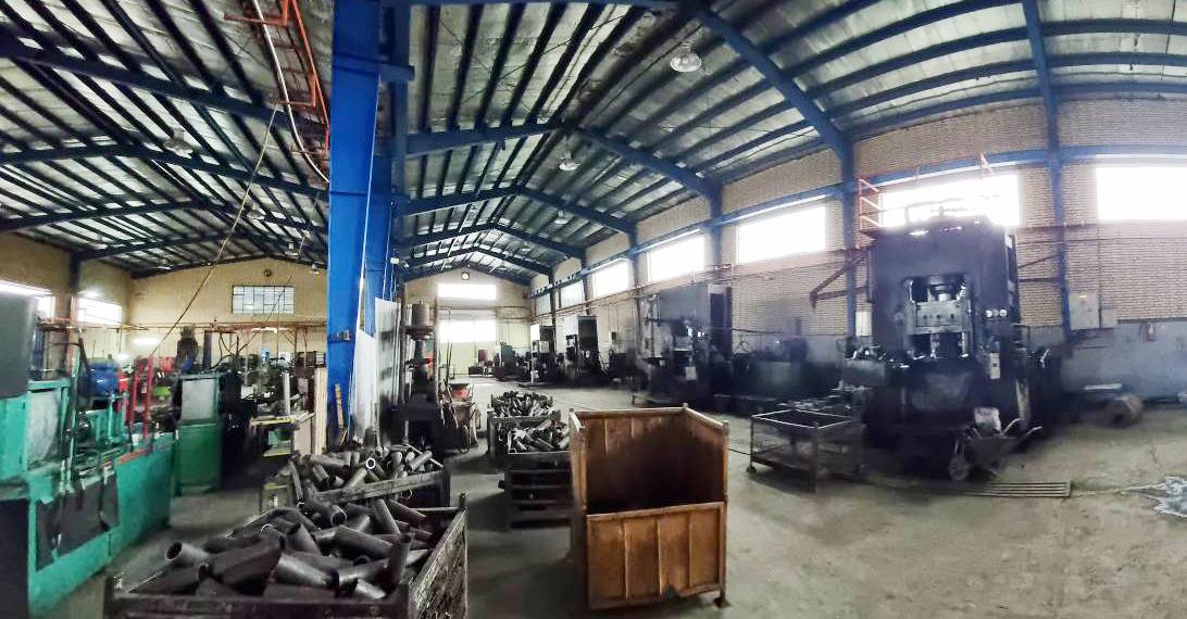
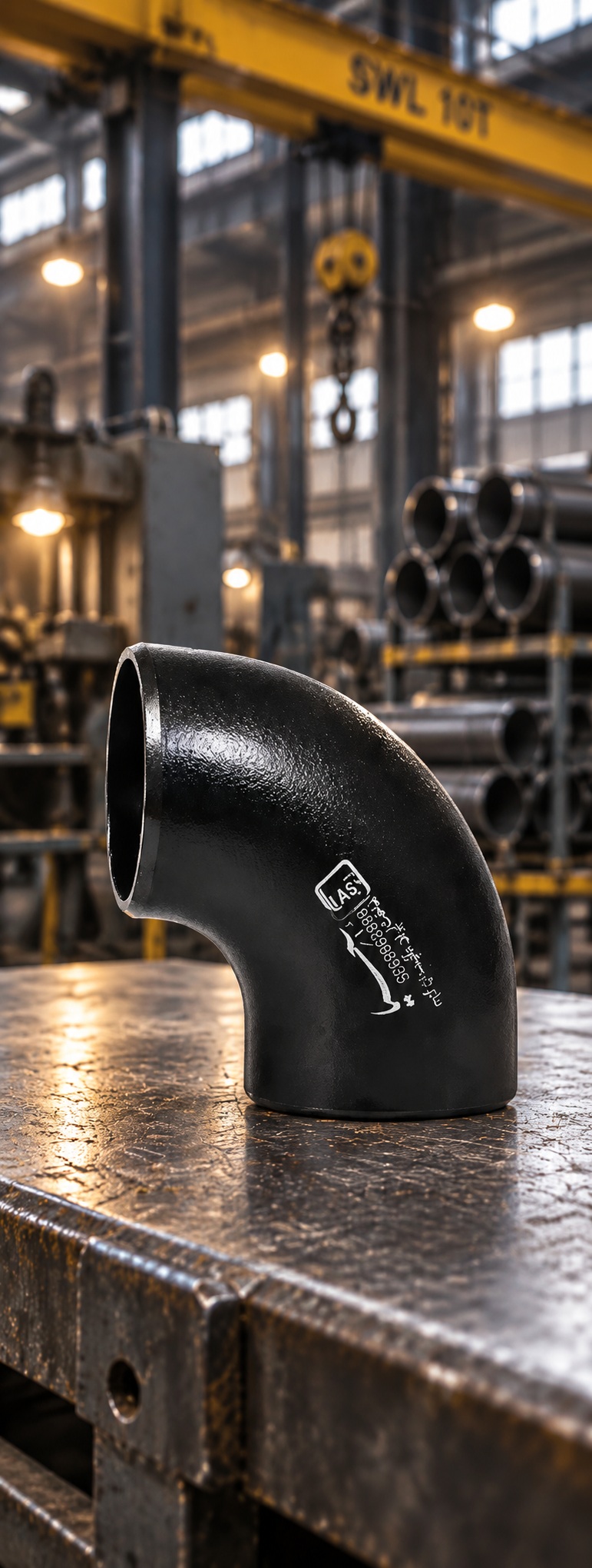
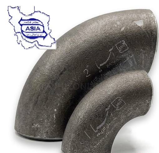
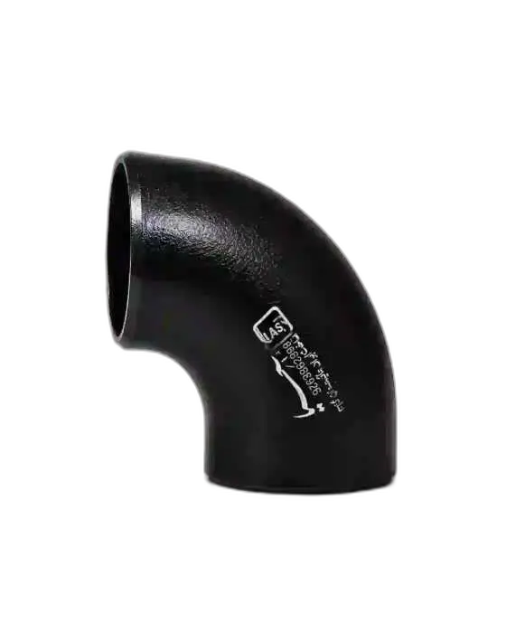
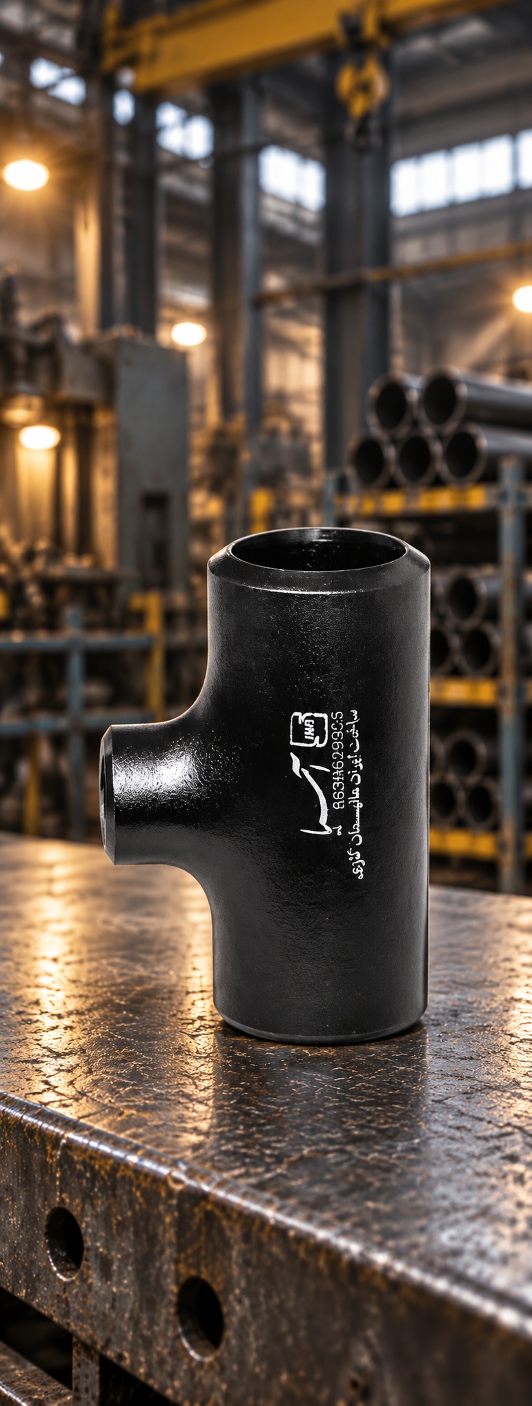
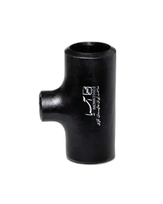
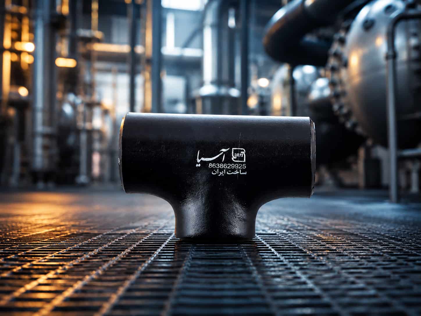
INDUSTRIAL PIPING SOLUTIONS
BUTT WELD
PIPE FITTINGS
Seamless & Welded Pipe Fittings
for Oil, Gas, Petrochemical
and Industrial Piping Systems
IRAN ETASAL ASIA
Manufacturer & Supplier of Steel Butt-Weld Pipe Fittings
iranetesal.com
TECHNICAL
CATALOG
03
PRODUCT OVERVIEW
Iran Etasal Asia supplies butt weld pipe fittings for demanding industrial piping applications.
Our product range includes elbows, tees, reducers, stub ends and caps in various
sizes, materials and schedules. We manufacture fittings from 1/2" up to 48" in both seamless and welded constructions.
TECHNICAL COVERAGE
Dimensions · Weight · Material · Schedule · Standards · Applications
ASMEB16.9
ASTMA234 / A403
MSSSP-25 / SP-43
📐 Manufacturing Capacity
1/2" – 48" NPS
09 · REFERENCE SECTION
STANDARDS & DIMENSIONS
ASME B16.9 · ASTM A234 · ASTM A403 · MSS SP-43
REFERENCE
STANDARDS
Select a product category below to view detailed dimensional tables, tolerances,
material specifications and applicable standards for each type of butt weld fitting.
About This Section
All dimensional tables and tolerances in this catalog are based on ASME B16.9
(Factory-Made Wrought Buttwelding Fittings) unless otherwise stated. Material specifications
follow ASTM A234 (carbon & alloy steel) and ASTM A403 (stainless steel).
10.2
DIMENSIONAL TOLERANCES
ELBOWS 45° & 90° LR & 3D · ASME B16.9
The following tolerances apply to butt weld elbows 45° and 90° LR and 3D,
manufactured to ASME B16.9. All tolerances are in millimeters unless otherwise
indicated and are equal ± except as noted.
Group 1 — NPS 1/2 to 8
mm
| Item |
1/2 to 2½ |
3 to 3½ |
4 |
5 to 8 |
| Outside Diameter at Bevel (D) | + 1.6 / − 0.8 | 1.6 | 1.6 | + 2.4 / − 1.6 |
| Inside Diameter at End | 0.8 | 1.6 | 1.6 | 1.6 |
| Center to End LR (A/B) | 2 | 2 | 2 | 2 |
| Center to End 3D (A/B) | 3 | 3 | 3 | 3 |
Group 2 — NPS 10 to 48
mm
| Item |
10 to 18 |
20 to 24 |
26 to 30 |
32 to 48 |
| Outside Diameter at Bevel (D) | + 4 / − 3.2 | + 6.4 / − 4.8 | + 6.4 / − 4.8 | + 6.4 / − 4.8 |
| Inside Diameter at End | 3.2 | 4.8 | + 6.4 / − 4.8 | + 6.4 / − 4.8 |
| Center to End LR (A/B) | 2 | 2 | 3 | 5 |
| Center to End 3D (A/B) | 3 | 3 | 6 | 6 |
| Wall Thickness (t) | Not less than 87.5% of Nominal Wall Thickness |
Notes
- Dimensional tolerances are in millimeters unless otherwise indicated.
- All tolerances are equal ± except as noted.
- Wall thickness (t) must be specified by customer.
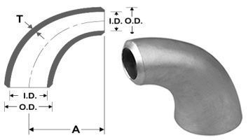
- Center to End LR (A/B) refers to the distance from the centerline of the fitting to the end of the fitting.
- For other sizes or special requirements, please contact our technical department.
10.3
SHORT RADIUS ELBOWS 90°
BUTT WELD · ASME B16.9
Short radius 90° elbows for compact piping layouts where space is limited.
Manufactured to ASME B16.9 from carbon, stainless and alloy steels.
Available from 1" to 24" NPS.
| NPS |
O.D.
(D) |
CTE
(A) |
| 1 | 33.4 | 25 |
| 1¼ | 42.2 | 32 |
| 1½ | 48.3 | 38 |
| 2 | 60.3 | 51 |
| 2½ | 73.0 | 64 |
| 3 | 88.9 | 76 |
| 3½ | 101.6 | 89 |
| 4 | 114.3 | 102 |
| 5 | 141.3 | 127 |
| 6 | 168.3 | 152 |
| NPS |
O.D.
(D) |
CTE
(A) |
| 8 | 219.1 | 203 |
| 10 | 273.0 | 254 |
| 12 | 323.8 | 305 |
| 14 | 355.6 | 356 |
| 16 | 406.4 | 406 |
| 18 | 457.0 | 457 |
| 20 | 508.0 | 508 |
| 22 | 559.0 | 559 |
| 24 | 610.0 | 610 |
| — | — | — |
Dimensions are in millimeters unless otherwise indicated. Wall thickness (t) must be specified by customer. *CTE = Center To End dimensions.
Dimensional Tolerances — 90° SR
ASME B16.9 · mm
| NPS |
1/2 to 2½ |
3 to 3½ |
4 |
5 to 8 |
| Outside Diameter at Bevel (D) | + 1.6 / − 0.8 | 1.6 | 1.6 | + 2.4 / − 1.6 |
| Inside Diameter at End | 0.8 | 1.6 | 1.6 | 1.6 |
| CTE (A) | 2 | 2 | 2 | 2 |
| NPS |
10 to 18 |
20 to 24 |
26 to 30 |
32 to 48 |
| Outside Diameter at Bevel (D) | + 4 / − 3.2 | + 6.4 / − 4.8 | + 6.4 / − 4.8 | + 6.4 / − 4.8 |
| Inside Diameter at End | 3.2 | 4.8 | + 6.4 / − 4.8 | + 6.4 / − 4.8 |
| CTE (A) | 2 | 2 | 3 | 5 |
| Wall Thickness (t) | Not less than 87.5% of Nominal Wall Thickness |
Dimensional tolerances are in millimeters unless otherwise indicated and are equal ± except as noted.
10.4
180° RETURN BENDS
LONG RADIUS & SHORT RADIUS · ASME B16.9
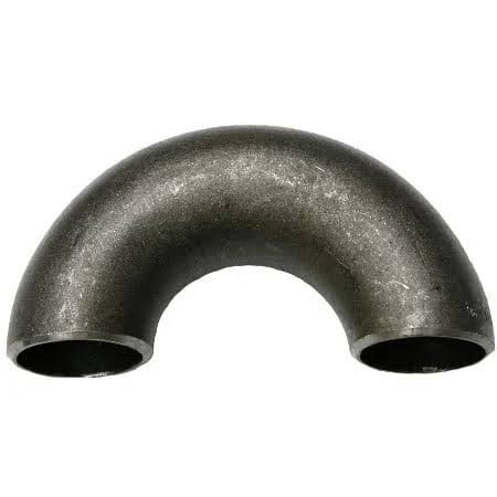
180° return bends available in both long radius and short radius configurations.
Used for reversing flow direction in piping systems. Manufactured to
ASME B16.9 from carbon, stainless and alloy steels.
| NPS |
O.D.
(D) |
180° LR |
180° SR |
C to C
(O) |
B to F
(K) |
C to C
(O) |
B to F
(K) |
| 1/2 | 21.3 | 76 | 48 | — | — |
| 3/4 | 26.7 | 76 | 51 | — | — |
| 1 | 33.4 | 76 | 56 | 51 | 41 |
| 1¼ | 42.2 | 95 | 70 | 64 | 52 |
| 1½ | 48.3 | 114 | 83 | 76 | 62 |
| 2 | 60.3 | 152 | 106 | 102 | 81 |
| 2½ | 73.0 | 190 | 132 | 127 | 100 |
| 3 | 88.9 | 229 | 159 | 152 | 121 |
| 3½ | 101.6 | 267 | 184 | 178 | 140 |
| 4 | 114.3 | 305 | 210 | 203 | 159 |
| 5 | 141.3 | 381 | 262 | 254 | 197 |
| 6 | 168.3 | 457 | 313 | 305 | 237 |
| 8 | 219.1 | 610 | 414 | 406 | 313 |
| 10 | 273.0 | 762 | 518 | 508 | 391 |
| NPS |
O.D.
(D) |
180° LR |
180° SR |
C to C
(O) |
B to F
(K) |
C to C
(O) |
B to F
(K) |
| 12 | 323.8 | 914 | 619 | 610 | 467 |
| 14 | 355.6 | 1067 | 711 | 711 | 533 |
| 16 | 406.4 | 1219 | 813 | 813 | 610 |
| 18 | 457.0 | 1372 | 914 | 914 | 686 |
| 20 | 508.0 | 1524 | 1016 | 1016 | 762 |
| 22 | 559.0 | 1676 | 1118 | 1118 | 838 |
| 24 | 610.0 | 1829 | 1219 | 1219 | 914 |
Dimensions are in millimeters unless otherwise indicated. Wall thickness (t) must be specified by customer.
*C to C = Center to Center · B to F = Back to Face.
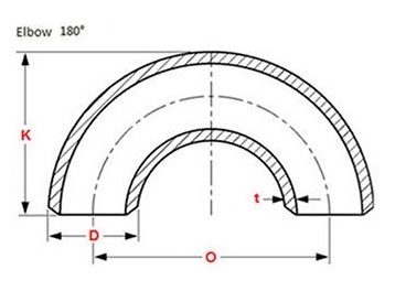
180° LR
Long radius return bends. Center to Center (O) and Back to Face (K).
180° SR
Short radius return bends. Available from 1" NPS.
STANDARD
ASME B16.9 · ASTM A234 WPB / A403 · MSS SP-43.
10.5
DIMENSIONAL TOLERANCES
ELBOWS 180° LR & SR · ASME B16.9
The following tolerances apply to butt weld return bends 180° long radius and
short radius, manufactured to ASME B16.9. All tolerances are in millimeters
unless otherwise indicated and are equal ± except as noted.
Group 1 — NPS 1/2 to 8
mm
| Item |
1/2 to 2½ |
3 to 3½ |
4 |
5 to 8 |
| Outside Diameter at Bevel (D) | + 1.6 / − 0.8 | 1.6 | 1.6 | + 2.4 / − 1.6 |
| Inside Diameter at End | 0.8 | 1.6 | 1.6 | 1.6 |
| Center to Center (O) | 6 | 6 | 6 | 6 |
| Back to Face (K) | 6 | 6 | 6 | 6 |
Group 2 — NPS 10 to 24
mm
| Item |
10 to 18 |
20 to 24 |
| Outside Diameter at Bevel (D) | + 4 / − 3.2 | + 6.4 / − 4.8 |
| Inside Diameter at End | 3.2 | 4.8 |
| Center to Center (O) | 10 | 10 |
| Back to Face (K) | 6 | 6 |
| Wall Thickness (t) | Not less than 87.5% of Nominal Wall Thickness |
Notes
- Dimensional tolerances are in millimeters unless otherwise indicated.
- All tolerances are equal ± except as noted.
- Wall thickness (t) must be specified by customer.
- Center to Center (O) refers to the distance between the two end faces of the return bend.
- Back to Face (K) refers to the distance from the back of the bend to the end face.
- MSS SP-43 only covers stainless steel buttweld fittings made for use with Schedule 5S and 10S pipe and Stub Ends suitable for use with Schedule 40S pipe, as defined in ASME B36.19. The dimensions and dimensional tolerances defined in MSS SP-43 are substantially the same as those in ASME B16.9 specifications from NPS 1/2 – NPS 24, except with regard to the outside diameter at the bevel.
10.6
90° LR REDUCING ELBOWS
BUTT WELD · ASME B16.9
Reducing 90° long radius elbows that change both direction and pipe size
in one fitting. Used where piping layout requires a combined turn and
reduction. Available from 4"×3" to 24"×12" NPS.
NPS
Red. × Run |
O.D.
Large |
O.D.
Small |
CTE
(A) |
| 4 × 3 | 114.3 | 88.9 | 152 |
| 4 × 2½ | 114.3 | 73.0 | 152 |
| 4 × 2 | 114.3 | 60.3 | 152 |
| 5 × 4 | 141.3 | 114.3 | 190 |
| 5 × 3½ | 141.3 | 101.6 | 190 |
| 5 × 3 | 141.3 | 88.9 | 190 |
| 5 × 2½ | 141.3 | 73.0 | 190 |
| 6 × 5 | 168.3 | 141.3 | 229 |
| 6 × 4 | 168.3 | 114.3 | 229 |
| 6 × 3½ | 168.3 | 101.6 | 229 |
| 6 × 3 | 168.3 | 88.9 | 229 |
| 8 × 6 | 219.1 | 168.3 | 305 |
| 8 × 5 | 219.1 | 141.3 | 305 |
| 8 × 4 | 219.1 | 114.3 | 305 |
| 10 × 8 | 273.0 | 219.1 | 381 |
| 10 × 6 | 273.0 | 168.3 | 381 |
| 10 × 5 | 273.0 | 141.3 | 381 |
| 12 × 10 | 323.8 | 273.0 | 457 |
| 12 × 8 | 323.8 | 219.1 | 457 |
| 12 × 6 | 323.8 | 168.3 | 457 |
| 14 × 12 | 355.6 | 323.8 | 533 |
| 14 × 10 | 355.6 | 273.0 | 533 |
| 14 × 8 | 355.6 | 219.1 | 533 |
NPS
Red. × Run |
O.D.
Large |
O.D.
Small |
CTE
(A) |
| 16 × 14 | 406.4 | 355.6 | 610 |
| 16 × 12 | 406.4 | 323.8 | 610 |
| 16 × 10 | 406.4 | 273.0 | 610 |
| 18 × 16 | 457.0 | 406.4 | 686 |
| 18 × 14 | 457.0 | 355.6 | 686 |
| 18 × 12 | 457.0 | 323.8 | 686 |
| 18 × 10 | 457.0 | 273.0 | 686 |
| 20 × 18 | 508.0 | 457.0 | 762 |
| 20 × 16 | 508.0 | 406.4 | 762 |
| 20 × 14 | 508.0 | 355.6 | 762 |
| 20 × 12 | 508.0 | 323.8 | 762 |
| 20 × 10 | 508.0 | 273.0 | 762 |
| 24 × 22 | 610.0 | 559.0 | 914 |
| 24 × 20 | 610.0 | 508.0 | 914 |
| 24 × 18 | 610.0 | 457.0 | 914 |
| 24 × 16 | 610.0 | 406.4 | 914 |
| 24 × 14 | 610.0 | 355.6 | 914 |
| 24 × 12 | 610.0 | 323.8 | 914 |
All dimensions are in millimeters unless otherwise indicated. Wall thickness (t) must be specified by customer.
REDUCING ELBOW
Combines direction change and pipe size reduction in one fitting.
CTE (A)
Center to End measured from the large end of the fitting.
STANDARD
ASME B16.9 · ASTM A234 WPB / A403 · MSS SP-43.
10.7
DIMENSIONAL TOLERANCES
REDUCING ELBOWS 90° LR · ASME B16.9
The following tolerances apply to butt weld reducing elbows 90° long radius,
manufactured to ASME B16.9. All tolerances are in millimeters unless otherwise
indicated and are equal ± except as noted.
Group 1 — NPS 1/2 to 8
mm
| Item |
1/2 to 2½ |
3 to 3½ |
4 |
5 to 8 |
| Outside Diameter at Bevel (D) | + 1.6 / − 0.8 | 1.6 | 1.6 | + 2.4 / − 1.6 |
| Inside Diameter at End | 0.8 | 1.6 | 1.6 | 1.6 |
| Center to End LR (A) | 2 | 2 | 2 | 2 |
Group 2 — NPS 10 to 24
mm
| Item |
10 to 18 |
20 to 24 |
| Outside Diameter at Bevel (D) | + 4 / − 3.2 | + 6.4 / − 4.8 |
| Inside Diameter at End | 3.2 | 4.8 |
| Center to End LR (A) | 2 | 2 |
| Wall Thickness (t) | Not less than 87.5% of Nominal Wall Thickness |
Notes
- Dimensional tolerances are in millimeters unless otherwise indicated.
- All tolerances are equal ± except as noted.
- Wall thickness (t) must be specified by customer.
- Center to End LR (A) refers to the distance from the centerline of the fitting to the end of the fitting.
- For reducing elbows, dimensions apply to the large end unless otherwise specified.
11.1
STRAIGHT TEES
BUTT WELD · ASME B16.9
Equal (straight) tees with equal run and branch dimensions. Used to branch
a piping system at 90° with equal pipe sizes. Manufactured to ASME B16.9
from carbon, stainless and alloy steels. Available from 1/2" to 48" NPS.
| NPS |
O.D.
(D) |
CTE
(C) |
CTE
(M) |
| 1/2 | 21.3 | 25 | 25 |
| 3/4 | 26.7 | 29 | 29 |
| 1 | 33.4 | 38 | 38 |
| 1¼ | 42.2 | 48 | 48 |
| 1½ | 48.3 | 57 | 57 |
| 2 | 60.3 | 64 | 64 |
| 2½ | 73.0 | 76 | 76 |
| 3 | 88.9 | 86 | 86 |
| 3½ | 101.6 | 95 | 95 |
| 4 | 114.3 | 105 | 105 |
| 5 | 141.3 | 124 | 124 |
| 6 | 168.3 | 143 | 143 |
| 8 | 219.1 | 178 | 178 |
| 10 | 273.0 | 216 | 216 |
| 12 | 323.8 | 254 | 254 |
| 14 | 355.6 | 279 | 279 |
| 16 | 406.4 | 305 | 305 |
| 18 | 457.0 | 343 | 343 |
| 20 | 508.0 | 381 | 381 |
| NPS |
O.D.
(D) |
CTE
(C) |
CTE
(M) |
| 22 | 559.0 | 419 | 419 |
| 24 | 610.0 | 432 | 432 |
| 26 | 660.0 | 495 | 495 |
| 28 | 711.0 | 521 | 521 |
| 30 | 762.0 | 559 | 559 |
| 32 | 813.0 | 597 | 597 |
| 34 | 864.0 | 635 | 635 |
| 36 | 914.0 | 673 | 673 |
| 38 | 965.0 | 711 | 711 |
| 40 | 1016.0 | 749 | 749 |
| 42 | 1067.0 | 762 | 711 |
| 44 | 1118.0 | 813 | 762 |
| 46 | 1168.0 | 851 | 800 |
| 48 | 1219.0 | 889 | 838 |
Dimensions are in millimeters unless otherwise indicated. Wall thickness (t) must be specified by customer.
Outlet dimension (M) for NPS 26 and larger is recommended but not required.
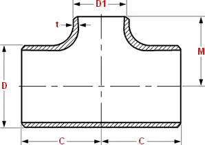
CTE (C)
Center to End of the run pipe.
CTE (M)
Center to End of the branch pipe.
STANDARD
ASME B16.9 · ASTM A234 WPB / A403 · MSS SP-43.
11.2
DIMENSIONAL TOLERANCES
STRAIGHT TEES · ASME B16.9
The following tolerances apply to butt weld straight tees, manufactured to
ASME B16.9. All tolerances are in millimeters unless otherwise indicated and
are equal ± except as noted.
Dimensional Tolerances
mm
| NPS |
1/2
to
2½ |
3
to
3½ |
4 |
5
to
8 |
10
to
18 |
20
to
24 |
26
to
30 |
32
to
48 |
| Outside Dia at Bevel (D) |
+1.6 / −0.8 |
1.6 |
1.6 |
+2.4 / −1.6 |
+4 / −3.2 |
+6.4 / −4.8 |
+6.4 / −4.8 |
+6.4 / −4.8 |
| Inside Dia at End |
0.8 |
1.6 |
1.6 |
1.6 |
3.2 |
4.8 |
+6.4 / −4.8 |
+6.4 / −4.8 |
| Center to End (C / M) |
2 |
2 |
2 |
2 |
2 |
2 |
3 |
5 |
| Wall Thk (t) |
Not less than 87.5% of Nominal Wall Thickness |
Notes
- Dimensional tolerances are in millimeters unless otherwise indicated.
- All tolerances are equal ± except as noted.
- Wall thickness (t) must be specified by customer.
- Center to End (C/M) applies to both the run (C) and branch (M) of the tee.
- MSS SP-43 only covers stainless steel buttweld fittings made for use with Schedule 5S and 10S pipe and Stub Ends suitable for use with Schedule 40S pipe, as defined in ASME B36.19. The dimensions and dimensional tolerances defined in MSS SP-43 are substantially the same as those in ASME B16.9 specifications from NPS 1/2 – NPS 24, except with regard to the outside diameter at the bevel.
11.3
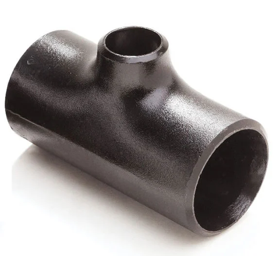
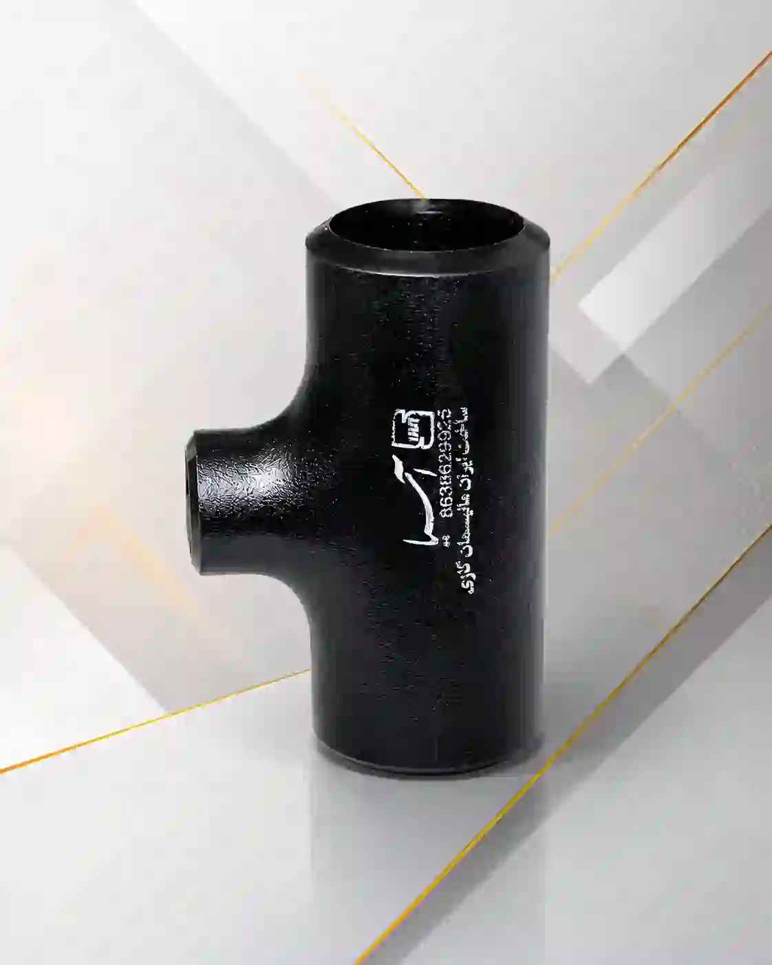
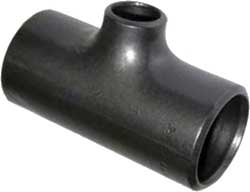
REDUCING TEES
BUTT WELD · ASME B16.9 · NPS 1/2 – 4
Reducing tees with different run and branch pipe sizes. Used to branch a piping
system where the branch size is smaller than the run. Manufactured to ASME B16.9.
NPS
Red × Run |
O.D.
(D) |
O.D.
(D1) |
CTE
(C) |
CTE
(M) |
| 3/4×1/2 | 26.7 | 21.3 | 29 | 29 |
| 1×1/2 | 33.4 | 21.3 | 38 | 38 |
| 1×3/4 | 33.4 | 26.7 | 38 | 38 |
| 1¼×1/2 | 42.2 | 21.3 | 48 | 48 |
| 1¼×3/4 | 42.2 | 26.7 | 48 | 48 |
| 1¼×1 | 42.2 | 33.4 | 48 | 48 |
| 1½×1/2 | 48.3 | 21.3 | 57 | 57 |
| 1½×3/4 | 48.3 | 26.7 | 57 | 57 |
| 1½×1 | 48.3 | 33.4 | 57 | 57 |
| 1½×1¼ | 48.3 | 42.2 | 57 | 57 |
| 2×3/4 | 60.3 | 26.7 | 64 | 44 |
| 2×1 | 60.3 | 33.4 | 64 | 51 |
| 2×1¼ | 60.3 | 42.2 | 64 | 57 |
| 2×1½ | 60.3 | 48.3 | 64 | 60 |
| 2½×1 | 73.0 | 33.4 | 76 | 57 |
NPS
Red × Run |
O.D.
(D) |
O.D.
(D1) |
CTE
(C) |
CTE
(M) |
| 2½×1¼ | 73.0 | 42.2 | 76 | 64 |
| 2½×1½ | 73.0 | 48.3 | 76 | 67 |
| 2½×2 | 73.0 | 60.3 | 76 | 70 |
| 3×1¼ | 88.9 | 42.2 | 86 | 70 |
| 3×1½ | 88.9 | 48.3 | 86 | 73 |
| 3×2 | 88.9 | 60.3 | 86 | 76 |
| 3×2½ | 88.9 | 73.0 | 86 | 83 |
| 3½×1½ | 101.6 | 48.3 | 95 | 79 |
| 3½×2 | 101.6 | 60.3 | 95 | 83 |
| 3½×2½ | 101.6 | 73.0 | 95 | 89 |
| 3½×3 | 101.6 | 88.9 | 95 | 92 |
| 4×1½ | 114.3 | 48.3 | 105 | 86 |
| 4×2 | 114.3 | 60.3 | 105 | 89 |
| 4×2½ | 114.3 | 73.0 | 105 | 95 |
| 4×3 | 114.3 | 88.9 | 105 | 98 |
| 4×3½ | 114.3 | 101.6 | 105 | 102 |
Dimensions are in millimeters unless otherwise indicated. Wall thickness (t) must be specified by customer.
CTE (C)
Center to End of the run pipe.
CTE (M)
Center to End of the branch pipe.
STANDARD
ASME B16.9 · ASTM A234 / A403.
11.4
REDUCING TEES
BUTT WELD · ASME B16.9 · NPS 5 – 16
Reducing tees for run sizes 5" through 16" with various branch sizes.
Manufactured to ASME B16.9 from carbon, stainless and alloy steels.
NPS
Red × Run |
O.D.
(D) |
O.D.
(D1) |
CTE
(C) |
CTE
(M) |
| 5 × 2 | 141.3 | 60.3 | 124 | 105 |
| 5 × 2½ | 141.3 | 73.0 | 124 | 108 |
| 5 × 3 | 141.3 | 88.9 | 124 | 111 |
| 5 × 3½ | 141.3 | 101.6 | 124 | 114 |
| 5 × 4 | 141.3 | 114.3 | 124 | 117 |
| 6 × 2½ | 168.3 | 73.0 | 143 | 121 |
| 6 × 3 | 168.3 | 88.9 | 143 | 124 |
| 6 × 3½ | 168.3 | 101.6 | 143 | 127 |
| 6 × 4 | 168.3 | 114.3 | 143 | 130 |
| 6 × 5 | 168.3 | 141.3 | 143 | 137 |
NPS
Red × Run |
O.D.
(D) |
O.D.
(D1) |
CTE
(C) |
CTE
(M) |
| 8 × 3½ | 219.1 | 101.6 | 178 | 152 |
| 8 × 4 | 219.1 | 114.3 | 178 | 156 |
| 8 × 5 | 219.1 | 141.3 | 178 | 162 |
| 8 × 6 | 219.1 | 168.3 | 178 | 168 |
| 10 × 4 | 273.0 | 114.3 | 216 | 184 |
| 10 × 5 | 273.0 | 141.3 | 216 | 191 |
| 10 × 6 | 273.0 | 168.3 | 216 | 194 |
| 10 × 8 | 273.0 | 219.1 | 216 | 203 |
| 12 × 5 | 323.8 | 141.3 | 254 | 216 |
| 12 × 6 | 323.8 | 168.3 | 254 | 219 |
| 12 × 8 | 323.8 | 219.1 | 254 | 229 |
| 12 × 10 | 323.8 | 273.0 | 254 | 241 |
| 14 × 6 | 355.6 | 168.3 | 279 | 238 |
| 14 × 8 | 355.6 | 219.1 | 279 | 248 |
| 14 × 10 | 355.6 | 273.0 | 279 | 257 |
| 14 × 12 | 355.6 | 323.8 | 279 | 270 |
| 16 × 6 | 406.4 | 168.3 | 305 | 264 |
| 16 × 8 | 406.4 | 219.1 | 305 | 273 |
| 16 × 10 | 406.4 | 273.0 | 305 | 283 |
| 16 × 12 | 406.4 | 323.8 | 305 | 295 |
| 16 × 14 | 406.4 | 355.6 | 305 | 305 |
Dimensions are in millimeters unless otherwise indicated. Wall thickness (t) must be specified by customer.
CTE (C)
Center to End of the run pipe.
CTE (M)
Center to End of the branch pipe.
STANDARD
ASME B16.9 · ASTM A234 / A403.
11.5
REDUCING TEES
BUTT WELD · ASME B16.9 · NPS 18 – 26
Reducing tees for run sizes 18" through 26" with various branch sizes.
Manufactured to ASME B16.9 from carbon, stainless and alloy steels.
NPS
Red × Run |
O.D.
(D) |
O.D.
(D1) |
CTE
(C) |
CTE
(M) |
| 18 × 8 | 457.0 | 219.1 | 343 | 298 |
| 18 × 10 | 457.0 | 273.0 | 343 | 308 |
| 18 × 12 | 457.0 | 323.8 | 343 | 321 |
| 18 × 14 | 457.0 | 355.6 | 343 | 330 |
| 18 × 16 | 457.0 | 406.4 | 343 | 330 |
| 20 × 8 | 508.0 | 219.1 | 381 | 324 |
| 20 × 10 | 508.0 | 273.0 | 381 | 333 |
| 20 × 12 | 508.0 | 323.8 | 381 | 346 |
| 20 × 14 | 508.0 | 355.6 | 381 | 356 |
| 20 × 16 | 508.0 | 406.4 | 381 | 356 |
| 20 × 18 | 508.0 | 457.0 | 381 | 368 |
| 22 × 10 | 559.0 | 273.0 | 419 | 359 |
| 22 × 12 | 559.0 | 323.8 | 419 | 371 |
| 22 × 14 | 559.0 | 355.6 | 419 | 381 |
| 22 × 16 | 559.0 | 406.4 | 419 | 381 |
NPS
Red × Run |
O.D.
(D) |
O.D.
(D1) |
CTE
(C) |
CTE
(M) |
| 22 × 18 | 559.0 | 457.0 | 419 | 394 |
| 22 × 20 | 559.0 | 508.0 | 419 | 406 |
| 24 × 10 | 610.0 | 273.0 | 432 | 384 |
| 24 × 12 | 610.0 | 323.8 | 432 | 397 |
| 24 × 14 | 610.0 | 355.6 | 432 | 406 |
| 24 × 16 | 610.0 | 406.4 | 432 | 406 |
| 24 × 18 | 610.0 | 457.0 | 432 | 419 |
| 24 × 20 | 610.0 | 508.0 | 432 | 432 |
| 24 × 22 | 610.0 | 559.0 | 432 | 432 |
| 26 × 12 | 660.0 | 323.8 | 495 | 422 |
| 26 × 14 | 660.0 | 355.6 | 495 | 432 |
| 26 × 16 | 660.0 | 406.4 | 495 | 432 |
| 26 × 18 | 660.0 | 457.0 | 495 | 444 |
| 26 × 20 | 660.0 | 508.0 | 495 | 457 |
| 26 × 22 | 660.0 | 559.0 | 495 | 470 |
| 26 × 24 | 660.0 | 610.0 | 495 | 483 |
Dimensions are in millimeters unless otherwise indicated. Wall thickness (t) must be specified by customer.
CTE (C)
Center to End of the run pipe.
CTE (M)
Center to End of the branch pipe.
STANDARD
ASME B16.9 · ASTM A234 / A403.
11.6
REDUCING TEES
BUTT WELD · ASME B16.9 · NPS 28 – 32
Reducing tees for run sizes 28" through 32" with various branch sizes.
Manufactured to ASME B16.9 from carbon, stainless and alloy steels.
NPS
Red × Run |
O.D.
(D) |
O.D.
(D1) |
CTE
(C) |
CTE
(M) |
| 28 × 12 | 711.0 | 323.8 | 521 | 448 |
| 28 × 14 | 711.0 | 355.6 | 521 | 457 |
| 28 × 16 | 711.0 | 406.4 | 521 | 457 |
| 28 × 18 | 711.0 | 457.0 | 521 | 470 |
| 28 × 20 | 711.0 | 508.0 | 521 | 483 |
| 28 × 22 | 711.0 | 559.0 | 521 | 495 |
| 28 × 24 | 711.0 | 610.0 | 521 | 508 |
| 28 × 26 | 711.0 | 660.0 | 521 | 521 |
| 30 × 10 | 762.0 | 273.0 | 559 | 460 |
| 30 × 12 | 762.0 | 323.8 | 559 | 473 |
| 30 × 14 | 762.0 | 355.6 | 559 | 483 |
| 30 × 16 | 762.0 | 406.4 | 559 | 483 |
| 30 × 18 | 762.0 | 457.0 | 559 | 495 |
NPS
Red × Run |
O.D.
(D) |
O.D.
(D1) |
CTE
(C) |
CTE
(M) |
| 30 × 20 | 762.0 | 508.0 | 559 | 508 |
| 30 × 22 | 762.0 | 559.0 | 559 | 521 |
| 30 × 24 | 762.0 | 610.0 | 559 | 533 |
| 30 × 26 | 762.0 | 660.0 | 559 | 546 |
| 30 × 28 | 762.0 | 711.0 | 559 | 546 |
| 32 × 14 | 813.0 | 355.6 | 597 | 508 |
| 32 × 16 | 813.0 | 406.4 | 597 | 508 |
| 32 × 18 | 813.0 | 457.0 | 597 | 521 |
| 32 × 20 | 813.0 | 508.0 | 597 | 533 |
| 32 × 22 | 813.0 | 559.0 | 597 | 546 |
| 32 × 24 | 813.0 | 610.0 | 597 | 559 |
| 32 × 26 | 813.0 | 660.0 | 597 | 572 |
| 32 × 28 | 813.0 | 711.0 | 597 | 572 |
| 32 × 30 | 813.0 | 762.0 | 597 | 584 |
Dimensions are in millimeters unless otherwise indicated. Wall thickness (t) must be specified by customer.
CTE (C)
Center to End of the run pipe.
CTE (M)
Center to End of the branch pipe.
STANDARD
ASME B16.9 · ASTM A234 / A403.
11.7
REDUCING TEES
BUTT WELD · ASME B16.9 · NPS 34 – 38
Reducing tees for run sizes 34" through 38" with various branch sizes.
Manufactured to ASME B16.9 from carbon, stainless and alloy steels.
NPS
Red × Run |
O.D.
(D) |
O.D.
(D1) |
CTE
(C) |
CTE
(M) |
| 34 × 16 | 864.0 | 406.4 | 635 | 533 |
| 34 × 18 | 864.0 | 457.0 | 635 | 546 |
| 34 × 20 | 864.0 | 508.0 | 635 | 559 |
| 34 × 22 | 864.0 | 559.0 | 635 | 572 |
| 34 × 24 | 864.0 | 610.0 | 635 | 584 |
| 34 × 26 | 864.0 | 660.0 | 635 | 597 |
| 34 × 28 | 864.0 | 711.0 | 635 | 597 |
| 34 × 30 | 864.0 | 762.0 | 635 | 610 |
| 34 × 32 | 864.0 | 813.0 | 635 | 622 |
| 36 × 16 | 914.0 | 406.4 | 673 | 559 |
| 36 × 18 | 914.0 | 457.0 | 673 | 572 |
NPS
Red × Run |
O.D.
(D) |
O.D.
(D1) |
CTE
(C) |
CTE
(M) |
| 36 × 20 | 914.0 | 508.0 | 673 | 584 |
| 36 × 22 | 914.0 | 559.0 | 673 | 597 |
| 36 × 24 | 914.0 | 610.0 | 673 | 610 |
| 36 × 26 | 914.0 | 660.0 | 673 | 622 |
| 36 × 28 | 914.0 | 711.0 | 673 | 622 |
| 36 × 30 | 914.0 | 762.0 | 673 | 635 |
| 36 × 32 | 914.0 | 813.0 | 673 | 648 |
| 36 × 34 | 914.0 | 864.0 | 673 | 660 |
| 38 × 18 | 965.0 | 457.0 | 711 | 597 |
| 38 × 20 | 965.0 | 508.0 | 711 | 610 |
| 38 × 22 | 965.0 | 559.0 | 711 | 622 |
| 38 × 24 | 965.0 | 610.0 | 711 | 635 |
| 38 × 26 | 965.0 | 660.0 | 711 | 648 |
| 38 × 28 | 965.0 | 711.0 | 711 | 648 |
| 38 × 30 | 965.0 | 762.0 | 711 | 673 |
| 38 × 32 | 965.0 | 813.0 | 711 | 686 |
| 38 × 34 | 965.0 | 864.0 | 711 | 698 |
| 38 × 36 | 965.0 | 914.0 | 711 | 711 |
Dimensions are in millimeters unless otherwise indicated. Wall thickness (t) must be specified by customer.
CTE (C)
Center to End of the run pipe.
CTE (M)
Center to End of the branch pipe.
STANDARD
ASME B16.9 · ASTM A234 / A403.
11.8
REDUCING TEES
BUTT WELD · ASME B16.9 · NPS 40 – 42
Reducing tees for run sizes 40" through 42" with various branch sizes.
Manufactured to ASME B16.9 from carbon, stainless and alloy steels.
NPS
Red × Run |
O.D.
(D) |
O.D.
(D1) |
CTE
(C) |
CTE
(M) |
| 40 × 18 | 1016.0 | 457.0 | 749 | 622 |
| 40 × 20 | 1016.0 | 508.0 | 749 | 635 |
| 40 × 22 | 1016.0 | 559.0 | 749 | 648 |
| 40 × 24 | 1016.0 | 610.0 | 749 | 660 |
| 40 × 26 | 1016.0 | 660.0 | 749 | 673 |
| 40 × 28 | 1016.0 | 711.0 | 749 | 673 |
| 40 × 30 | 1016.0 | 762.0 | 749 | 698 |
| 40 × 32 | 1016.0 | 813.0 | 749 | 711 |
| 40 × 34 | 1016.0 | 864.0 | 749 | 724 |
| 40 × 36 | 1016.0 | 914.0 | 749 | 737 |
| 40 × 38 | 1016.0 | 965.0 | 749 | 749 |
| 42 × 16 | 1067.0 | 406.4 | 762 | 635 |
| 42 × 18 | 1067.0 | 457.0 | 762 | 648 |
| 42 × 20 | 1067.0 | 508.0 | 762 | 660 |
NPS
Red × Run |
O.D.
(D) |
O.D.
(D1) |
CTE
(C) |
CTE
(M) |
| 42 × 22 | 1067.0 | 559.0 | 762 | 660 |
| 42 × 24 | 1067.0 | 610.0 | 762 | 660 |
| 42 × 26 | 1067.0 | 660.0 | 762 | 698 |
| 42 × 28 | 1067.0 | 711.0 | 762 | 698 |
| 42 × 30 | 1067.0 | 762.0 | 762 | 711 |
| 42 × 32 | 1067.0 | 813.0 | 762 | 711 |
| 42 × 34 | 1067.0 | 864.0 | 762 | 711 |
| 42 × 36 | 1067.0 | 914.0 | 762 | 711 |
| 42 × 38 | 1067.0 | 965.0 | 762 | 711 |
| 42 × 40 | 1067.0 | 1016.0 | 762 | 711 |
Dimensions are in millimeters unless otherwise indicated. Wall thickness (t) must be specified by customer.
CTE (C)
Center to End of the run pipe.
CTE (M)
Center to End of the branch pipe.
STANDARD
ASME B16.9 · ASTM A234 / A403.
11.9
REDUCING TEES
BUTT WELD · ASME B16.9 · NPS 44 – 48
Reducing tees for run sizes 44" through 48" with various branch sizes.
Manufactured to ASME B16.9 from carbon, stainless and alloy steels.
NPS
Red × Run |
O.D.
(D) |
O.D.
(D1) |
CTE
(C) |
CTE
(M) |
| 44 × 20 | 1118 | 508 | 813 | 686 |
| 44 × 22 | 1118 | 559 | 813 | 686 |
| 44 × 24 | 1118 | 610 | 813 | 698 |
| 44 × 26 | 1118 | 660 | 813 | 698 |
| 44 × 28 | 1118 | 711 | 813 | 698 |
| 44 × 30 | 1118 | 762 | 813 | 711 |
| 44 × 32 | 1118 | 813 | 813 | 711 |
| 44 × 34 | 1118 | 864 | 813 | 724 |
| 44 × 36 | 1118 | 914 | 813 | 724 |
| 44 × 38 | 1118 | 965 | 813 | 737 |
| 44 × 40 | 1118 | 1016 | 813 | 749 |
| 44 × 42 | 1118 | 1067 | 813 | 762 |
| 46 × 22 | 1168 | 559 | 851 | 724 |
| 46 × 24 | 1168 | 610 | 851 | 724 |
| 46 × 26 | 1168 | 660 | 851 | 737 |
| 46 × 28 | 1168 | 711 | 851 | 737 |
| 46 × 30 | 1168 | 762 | 851 | 737 |
| 46 × 32 | 1168 | 813 | 851 | 749 |
| 46 × 34 | 1168 | 864 | 851 | 749 |
| 46 × 36 | 1168 | 914 | 851 | 762 |
| 46 × 38 | 1168 | 965 | 851 | 762 |
NPS
Red × Run |
O.D.
(D) |
O.D.
(D1) |
CTE
(C) |
CTE
(M) |
| 46 × 40 | 1168 | 1016 | 851 | 775 |
| 46 × 42 | 1168 | 1067 | 851 | 787 |
| 46 × 44 | 1168 | 1118 | 851 | 800 |
| 48 × 22 | 1219 | 559 | 889 | 737 |
| 48 × 24 | 1219 | 610 | 889 | 737 |
| 48 × 26 | 1219 | 660 | 889 | 762 |
| 48 × 28 | 1219 | 711 | 889 | 762 |
| 48 × 30 | 1219 | 762 | 889 | 762 |
| 48 × 32 | 1219 | 813 | 889 | 787 |
| 48 × 34 | 1219 | 864 | 889 | 787 |
| 48 × 36 | 1219 | 914 | 889 | 787 |
| 48 × 38 | 1219 | 965 | 889 | 813 |
| 48 × 40 | 1219 | 1016 | 889 | 813 |
| 48 × 42 | 1219 | 1067 | 889 | 813 |
| 48 × 44 | 1219 | 1118 | 889 | 838 |
| 48 × 46 | 1219 | 1168 | 889 | 838 |
Dimensions are in millimeters unless otherwise indicated. Wall thickness (t) must be specified by customer.
CTE (C)
Center to End of the run pipe.
CTE (M)
Center to End of the branch pipe.
STANDARD
ASME B16.9 · ASTM A234 / A403.
12.1
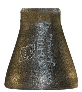
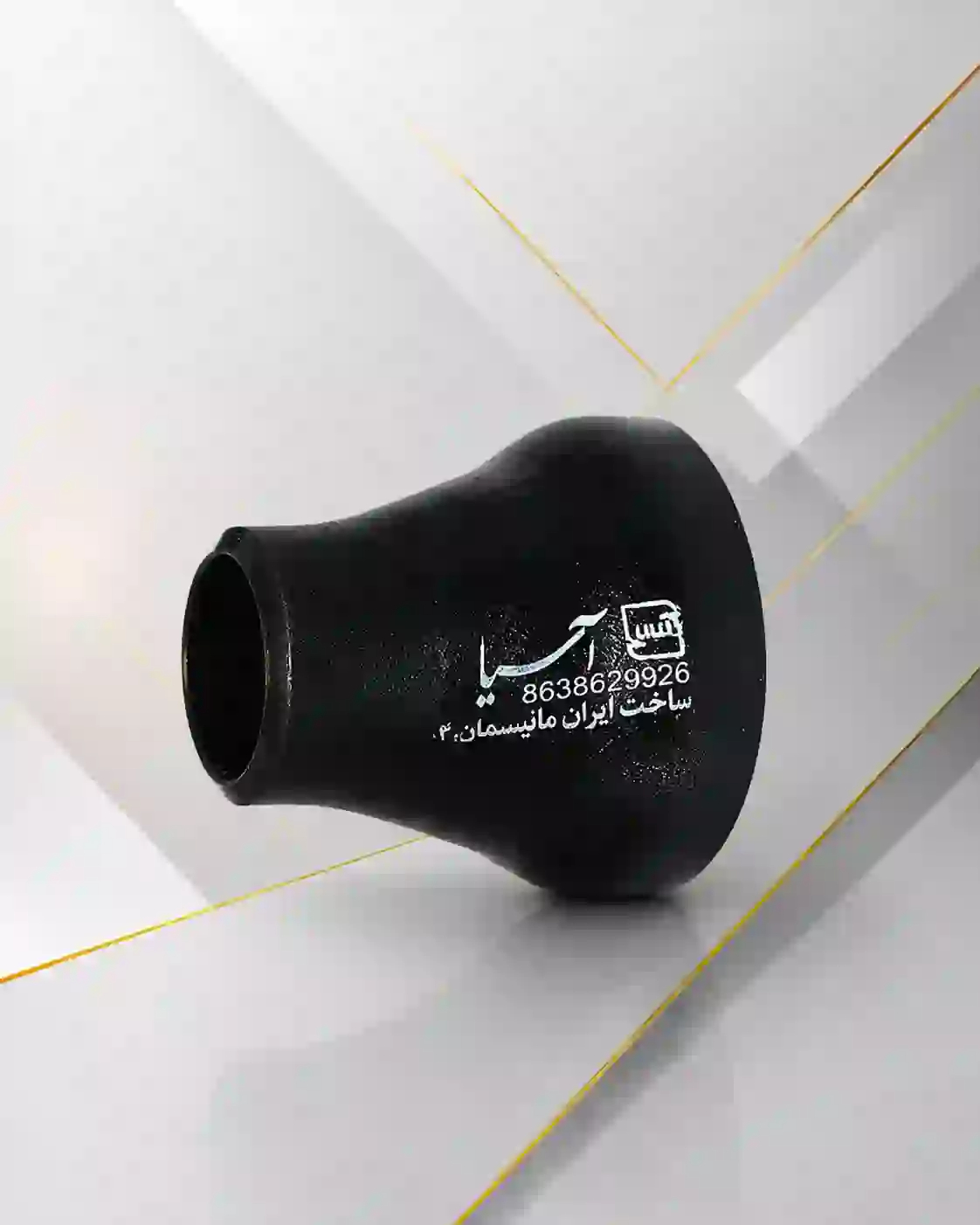
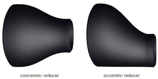
REDUCERS
CONCENTRIC & ECCENTRIC · BUTT WELD · ASME B16.9
Concentric and eccentric reducers from NPS ¾ through 12, with various reduced sizes.
Manufactured to ASME B16.9 from carbon, stainless and alloy steels.
NPS
Red × Run |
O.D.
(D) |
O.D.
(D1) |
Length
(H) |
| ¾ × ½ | 26.7 | 21.3 | 38 |
| 1 × ½ | 33.4 | 21.3 | 51 |
| 1 × ¾ | 33.4 | 26.7 | 51 |
| 1¼ × ½ | 42.2 | 21.3 | 51 |
| 1¼ × ¾ | 42.2 | 26.7 | 51 |
| 1¼ × 1 | 42.2 | 33.4 | 51 |
| 1½ × ½ | 48.3 | 21.3 | 64 |
| 1½ × ¾ | 48.3 | 26.7 | 64 |
| 1½ × 1 | 48.3 | 33.4 | 64 |
| 1½ × 1¼ | 48.3 | 42.2 | 64 |
| 2 × ¾ | 60.3 | 26.7 | 76 |
| 2 × 1 | 60.3 | 33.4 | 76 |
| 2 × 1¼ | 60.3 | 42.2 | 76 |
| 2 × 1½ | 60.3 | 48.3 | 76 |
| 2½ × 1 | 73 | 33.4 | 89 |
| 2½ × 1¼ | 73 | 42.2 | 89 |
| 2½ × 1½ | 73 | 48.3 | 89 |
| 2½ × 2 | 73 | 60.3 | 89 |
| 3 × 1¼ | 88.9 | 42.2 | 89 |
| 3 × 1½ | 88.9 | 48.3 | 89 |
| 3 × 2 | 88.9 | 60.3 | 89 |
| 3 × 2½ | 88.9 | 73 | 89 |
| 3½ × 1¼ | 101.6 | 42.2 | 102 |
| 3½ × 1½ | 101.6 | 48.3 | 102 |
| 3½ × 2 | 101.6 | 60.3 | 102 |
| 3½ × 2½ | 101.6 | 73 | 102 |
| 3½ × 3 | 101.6 | 88.9 | 102 |
NPS
Red × Run |
O.D.
(D) |
O.D.
(D1) |
Length
(H) |
| 4 × 1½ | 114.3 | 48.3 | 102 |
| 4 × 2 | 114.3 | 60.3 | 102 |
| 4 × 2½ | 114.3 | 73 | 102 |
| 4 × 3 | 114.3 | 88.9 | 102 |
| 4 × 3½ | 114.3 | 101.6 | 102 |
| 5 × 2 | 141.3 | 60.3 | 127 |
| 5 × 2½ | 141.3 | 73 | 127 |
| 5 × 3 | 141.3 | 88.9 | 127 |
| 5 × 3½ | 141.3 | 101.6 | 127 |
| 5 × 4 | 141.3 | 114.3 | 127 |
| 6 × 2½ | 168.3 | 73 | 140 |
| 6 × 3 | 168.3 | 88.9 | 140 |
| 6 × 3½ | 168.3 | 101.6 | 140 |
| 6 × 4 | 168.3 | 114.3 | 140 |
| 6 × 5 | 168.3 | 141.3 | 140 |
| 8 × 3½ | 219.1 | 101.6 | 152 |
| 8 × 4 | 219.1 | 114.3 | 152 |
| 8 × 5 | 219.1 | 141.3 | 152 |
| 8 × 6 | 219.1 | 168.3 | 152 |
| 10 × 4 | 273 | 114.3 | 178 |
| 10 × 5 | 273 | 141.3 | 178 |
| 10 × 6 | 273 | 168.3 | 178 |
| 10 × 8 | 273 | 219.1 | 178 |
| 12 × 5 | 323.9 | 141.3 | 203 |
| 12 × 6 | 323.9 | 168.3 | 203 |
| 12 × 8 | 323.9 | 219.1 | 203 |
| 12 × 10 | 323.9 | 273 | 203 |
Dimensions are in millimeters unless otherwise indicated. Wall thickness (t) must be specified by customer.
O.D. (D)
Outside diameter of large end.
O.D. (D1)
Outside diameter of small end.
STANDARD
ASME B16.9 · ASTM A234 / A403.
12.2
REDUCERS
CONCENTRIC & ECCENTRIC · BUTT WELD · ASME B16.9
Concentric and eccentric reducers from NPS 14 through 40, with various reduced sizes.
Manufactured to ASME B16.9 from carbon, stainless and alloy steels.
NPS
Red × Run |
O.D.
(D) |
O.D.
(D1) |
Length
(H) |
| 14 × 6 | 355.6 | 168.3 | 330 |
| 14 × 8 | 355.6 | 219.1 | 330 |
| 14 × 10 | 355.6 | 273 | 330 |
| 14 × 12 | 355.6 | 323.9 | 330 |
| 16 × 8 | 406.4 | 219 | 356 |
| 16 × 10 | 406.4 | 273 | 356 |
| 16 × 12 | 406.4 | 323.9 | 356 |
| 16 × 14 | 406.4 | 355.6 | 356 |
| 18 × 10 | 457 | 273 | 381 |
| 18 × 12 | 457 | 323.9 | 381 |
| 18 × 14 | 457 | 355.6 | 381 |
| 18 × 16 | 457 | 406.4 | 381 |
| 20 × 12 | 508 | 323.9 | 508 |
| 20 × 14 | 508 | 355.6 | 508 |
| 20 × 16 | 508 | 406.4 | 508 |
| 20 × 18 | 508 | 457 | 508 |
| 22 × 14 | 559 | 355.6 | 508 |
| 22 × 16 | 559 | 406.4 | 508 |
| 22 × 18 | 559 | 457 | 508 |
| 22 × 20 | 559 | 508 | 508 |
| 24 × 16 | 610 | 406.4 | 508 |
| 24 × 18 | 610 | 457 | 508 |
| 24 × 20 | 610 | 508 | 508 |
| 24 × 22 | 610 | 559 | 508 |
| 26 × 18 | 660 | 457 | 610 |
| 26 × 20 | 660 | 508 | 610 |
| 26 × 22 | 660 | 559 | 610 |
| 26 × 24 | 660 | 610 | 610 |
| 28 × 18 | 711 | 457 | 610 |
| 28 × 20 | 711 | 508 | 610 |
NPS
Red × Run |
O.D.
(D) |
O.D.
(D1) |
Length
(H) |
| 28 × 24 | 711 | 610 | 610 |
| 28 × 26 | 711 | 660 | 610 |
| 30 × 20 | 762 | 508 | 610 |
| 30 × 24 | 762 | 610 | 610 |
| 30 × 26 | 762 | 660 | 610 |
| 30 × 28 | 762 | 711 | 610 |
| 32 × 24 | 813 | 610 | 610 |
| 32 × 26 | 813 | 660 | 610 |
| 32 × 28 | 813 | 711 | 610 |
| 32 × 30 | 813 | 762 | 610 |
| 34 × 24 | 864 | 610 | 610 |
| 34 × 26 | 864 | 660 | 610 |
| 34 × 30 | 864 | 762 | 610 |
| 34 × 32 | 864 | 813 | 610 |
| 36 × 24 | 914 | 610 | 610 |
| 36 × 26 | 914 | 660 | 610 |
| 36 × 30 | 914 | 762 | 610 |
| 36 × 32 | 914 | 813 | 610 |
| 36 × 34 | 914 | 864 | 610 |
| 38 × 26 | 965 | 660 | 610 |
| 38 × 28 | 965 | 711 | 610 |
| 38 × 30 | 965 | 762 | 610 |
| 38 × 32 | 965 | 813 | 610 |
| 38 × 34 | 965 | 864 | 610 |
| 38 × 36 | 965 | 914 | 610 |
| 40 × 30 | 1016 | 762 | 610 |
| 40 × 32 | 1016 | 813 | 610 |
| 40 × 34 | 1016 | 864 | 610 |
| 40 × 36 | 1016 | 914 | 610 |
| 40 × 38 | 1016 | 965 | 610 |
Dimensions are in millimeters unless otherwise indicated. Wall thickness (t) must be specified by customer.
12.3
REDUCERS — TOLERANCES
CONCENTRIC & ECCENTRIC · BUTT WELD · ASME B16.9
Dimensional tolerances for concentric and eccentric reducers according to ASME B16.9.
Tolerances are in millimeters unless otherwise indicated and are equal ± except as noted.
Nominal
Pipe Size |
O.D. at Bevel
(D) |
I.D. at End |
Overall
Length (H) |
| ½ to 2½ | + 1.6
− 0.8 | 0.8 | 2 |
| 3 to 3½ | 1.6 | 1.6 | 2 |
| 4 | 1.6 | 1.6 | 2 |
| 5 to 8 | + 2.4
− 1.6 | 1.6 | 2 |
Nominal
Pipe Size |
O.D. at Bevel
(D) |
I.D. at End |
Overall
Length (H) |
| 10 to 18 | + 4
− 3.2 | 3.2 | 2 |
| 20 to 24 | + 6.4
− 4.8 | 4.8 | 2 |
| 26 to 30 | + 6.4
− 4.8 | + 6.4
− 4.8 | 5 |
| 32 to 48 | + 6.4
− 4.8 | + 6.4
− 4.8 | 5 |
WALL THICKNESS (t)
Not less than 87.5% of Nominal Wall Thickness.
Dimensional tolerances are in millimeters unless otherwise indicated and are equal ± except as noted.
NOTE
MSS SP-43 only covers stainless steel buttweld fittings made for use with Schedule 5S and 10S pipe and Stub Ends suitable for use with Schedule 40S pipe, as defined in ASME B36.19. The dimensions and dimensional tolerances defined in MSS SP-43 are substantially the same as those in ASME B16.9 specifications from NPS ½ – NPS 24, except with regard to the outside diameter at the bevel.
O.D. (D)
Outside diameter at bevel.
I.D. at End
Inside diameter at end.
STANDARD
ASME B16.9 · ASTM A234 / A403.
13.2
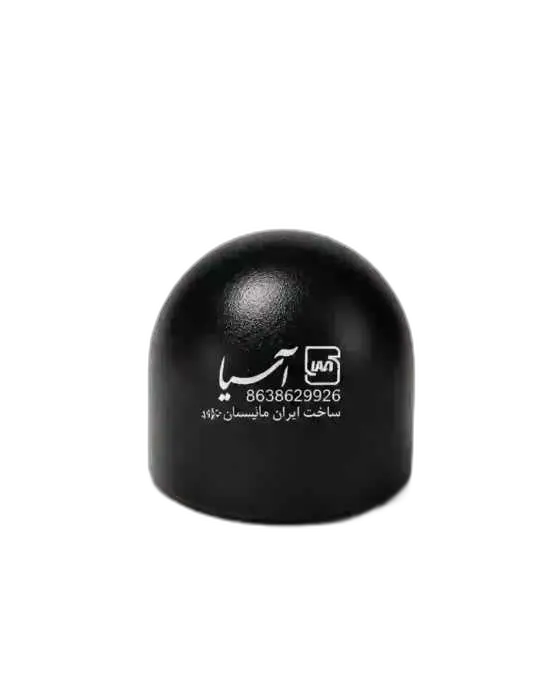
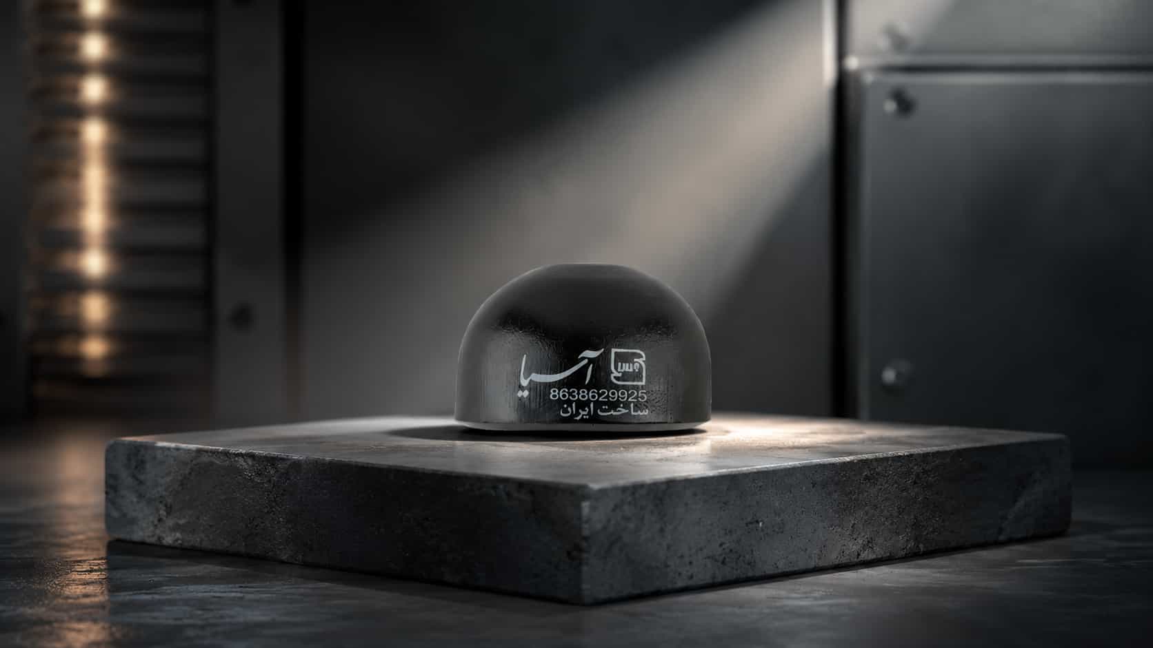
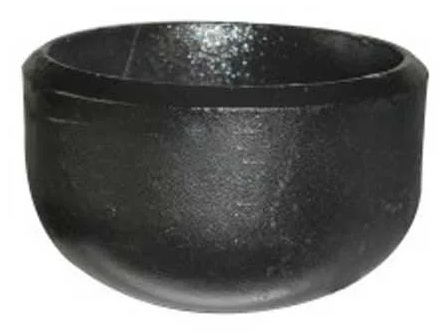
CAPS — TOLERANCES
BUTT WELD · ASME B16.9
Dimensional tolerances for butt weld pipe caps according to ASME B16.9.
Tolerances are in millimeters unless otherwise indicated and are equal ± except as noted.
Tolerances — NPS ½ to 8
Nominal
Pipe Size |
Outside Diameter
at Bevel (D) |
Inside Diameter
at End |
Overall
Length (H) |
| ½ to 2½ | + 1.6
− 0.8 | 0.8 | 3 |
| 3 to 3½ | 1.6 | 1.6 | 3 |
| 4 | 1.6 | 1.6 | 3 |
| 5 to 8 | + 2.4
− 1.6 | 1.6 | 6 |
Tolerances — NPS 10 to 48
Nominal
Pipe Size |
Outside Diameter
at Bevel (D) |
Inside Diameter
at End |
Overall
Length (H) |
| 10 to 18 | + 4
− 3.2 | 3.2 | 6 |
| 20 to 24 | + 6.4
− 4.8 | 4.8 | 6 |
| 26 to 30 | + 6.4
− 4.8 | + 6.4
− 4.8 | 10 |
| 32 to 48 | + 6.4
− 4.8 | + 6.4
− 4.8 | 10 |
WALL THICKNESS (t)
Not less than 87.5% of Nominal Wall Thickness.
Dimensional tolerances are in millimeters unless otherwise indicated and are equal ± except as noted.
NOTE
MSS SP-43 only covers stainless steel buttweld fittings made for use with Schedule 5S and 10S pipe and Stub Ends suitable for use with Schedule 40S pipe, as defined in ASME B36.19. The dimensions and dimensional tolerances defined in MSS SP-43 are substantially the same as those in ASME B16.9 specifications from NPS ½ – NPS 24, except with regard to the outside diameter at the bevel.
O.D. (D)
Outside diameter at bevel.
I.D. at End
Inside diameter at end.
STANDARD
ASME B16.9 · ASTM A234 / A403.
16
QUALITY & CERTIFICATIONS
Iran Etasal Asia is committed to delivering products that meet international quality
standards. Our manufacturing processes, materials and finished products are tested
and certified according to recognized industry specifications.
ASME
B16.9 — Factory-Made Wrought Buttwelding Fittings
B16.11 — Forged Fittings, Socket-Welding and Threaded
B16.5 — Pipe Flanges and Flanged Fittings
ASTM
A234 WPB — Carbon Steel
A403 — Stainless Steel
A420 — Low Temperature Steel
A234 — Alloy Steel
MSS
SP-25 — Standard Marking System
SP-43 — Wrought Stainless Steel Fittings
ISO
ISO 9001:2015 — Quality Management
ISO 14001:2015 — Environmental Management
Certification Marks
ISO
9001
API
6A
CE
PED
ASTM
🏭 Manufacturing Capability
Seamless & Welded — 1/2" to 48" NPS
All products are supplied with mill test certificates upon request. Additional
testing (radiographic, ultrasonic, hydrostatic) and third-party inspection
services are available. Please contact our technical department for further details.