
How to Select the Right Welded Pipe Fitting Based on the Welding Process
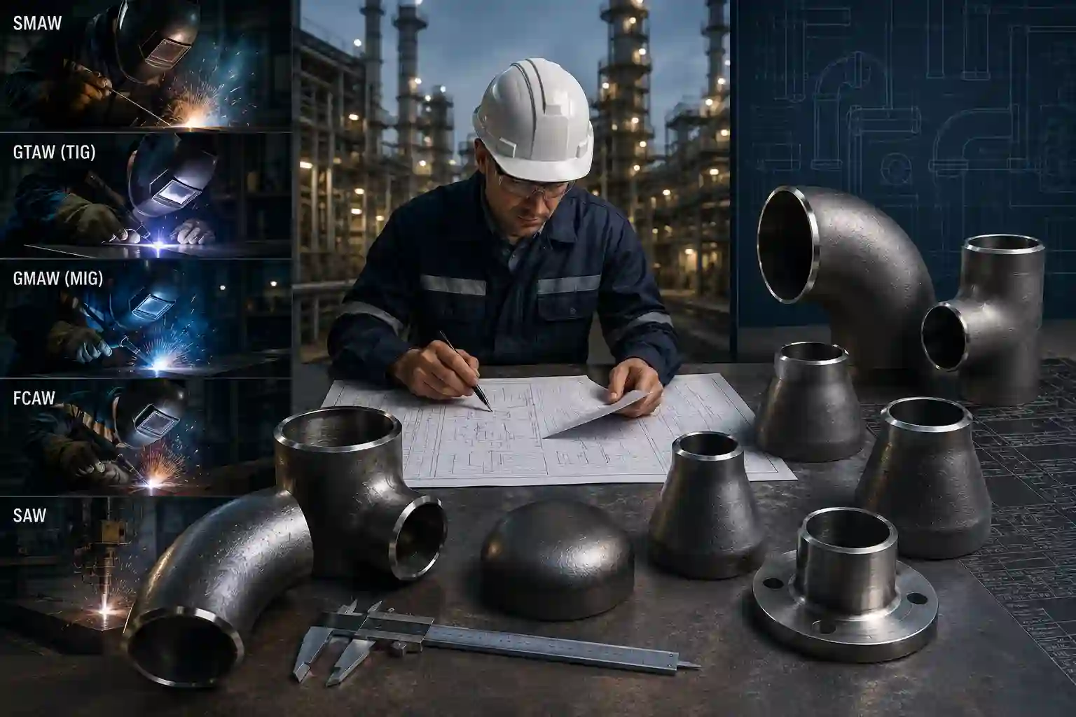
How to Select the Right Welded Pipe Fitting Based on the Welding Process
📑 Table of Contents
- PART 1 — FOUNDATIONS
- 1. Introduction
- 2. Why Choosing Matters
- 3. What Is a Welding Process?
- 4. Key Factors Affecting Selection
- 5. Material Selection
- 6. Pressure, Temperature & Fluid
- 7. Codes and Standards
- 8. Main Categories of Fittings
- 9. Butt vs Socket vs Threaded
- 10. Comparison Table
- PART 2 — BY WELDING PROCESS
- 11. SMAW
- 12. GTAW (TIG)
- 13. GMAW (MIG/MAG)
- 14. FCAW
- 15. SAW
- 16. Orbital Welding
- 17. High Pressure Systems
- 18. High Temperature Service
- 19. Corrosive Fluids
- 20. Oil & Gas, Petrochemical, Power
- 21. Common Selection Mistakes
- 22. Welding Process Comparison
- PART 3 — WORKFLOW & TOOLS
- 23. Step-by-Step Workflow
- 24. Engineering Checklist
- 25. Real Project Examples
- 26. Common Design Mistakes
- 27. Cost, Reliability, Performance
- 28. Inspection & Quality Control
- 29. FAQ
- 30. Conclusion
- 31. References
1. Introduction
Selecting the correct welded pipe fitting for a piping system is not a routine procurement decision. It is a fundamental engineering choice that directly influences the integrity, safety, and service life of the entire installation. In the oil and gas, petrochemical, and power generation industries, a single improperly selected fitting can lead to catastrophic failure, unplanned shutdowns, and significant financial loss.
The complexity of modern piping systems demands that engineers move beyond simple catalog matching. The selection process must consider material compatibility, pressure-temperature ratings, dimensional standards, and — critically — the welding process that will join the fitting to the adjacent pipe. Each welding process imposes specific requirements on the fitting's geometry, wall thickness, bevel design, and material behavior.
This comprehensive guide is organized into three integrated parts. Part 1 covers the essential foundations. Part 2 addresses welding process-specific selection criteria. Part 3 provides practical workflows, project examples, and engineering tools.
This part covers the essential building blocks: why fitting selection matters, what defines a welding process in this context, the key selection factors, material influence, pressure-temperature considerations, applicable codes, and the main categories of fittings. Subsequent parts build directly upon this foundation.
2. Why Choosing the Correct Welded Pipe Fitting Matters
The significance of proper welded pipe fitting selection extends beyond mere compliance with specifications. It affects every phase of a project lifecycle, from detailed engineering through construction, commissioning, and long-term operation.
2.1 Impact on System Integrity
A welded pipe fitting becomes an integral part of the pressure-containing boundary. Unlike flanged or threaded connections, welded joints do not permit disassembly. Once installed, the fitting and the pipe become a single continuous structure. Any weakness in the fitting, whether from incorrect material grade, insufficient wall thickness, or incompatible geometry, becomes a permanent vulnerability.
Pressure-containing components in process plants are subject to cyclic loading, thermal expansion, vibration, and corrosive environments. Fittings selected without due consideration to these service conditions are prone to premature failure modes including:
- Fatigue cracking at stress concentration points
- Creep deformation at high temperatures
- Corrosion erosion thinning in high-velocity services
- Brittle fracture during upset conditions
2.2 Effect on Fabrication and Construction
The wrong fitting selection directly impacts welding productivity and quality. Fittings with improper bevel angles, incorrect bore alignment, or inadequate wall transition create difficulties for the welding operator. These difficulties manifest as:
- Increased defect rates requiring repair
- Extended welding time and associated labor costs
- Higher consumable consumption
- Delays in critical path construction activities
Conversely, correctly selected fittings enable efficient, repeatable welding procedures and contribute to consistent joint quality across large-scale projects.
2.3 Lifecycle Cost Implications
Initial purchase price represents only a fraction of the total cost associated with a pipe fitting. Poor selection drives higher costs in:
- Installation labor and rework
- Quality control and nondestructive examination
- Future maintenance and inspection access
- Replacement during turnaround events
- Production losses from unplanned outages
Engineering organizations that invest time in proper fitting selection consistently report lower total installed costs and reduced operational expenditures over the facility lifecycle.
3. What Is a Welding Process?
In the context of pipe fitting selection, the term "welding process" refers to the specific method by which the fitting is joined to the connecting pipe. The selection of a welding process determines several critical parameters that directly influence the specification and procurement of fittings.
3.1 Definition and Scope
A welding process is a systematic procedure that uses heat, pressure, or both to produce coalescence between two metal components. For piping applications, the process establishes:
- The heat input profile delivered to the joint
- The cooling rate and resulting metallurgical transformation
- The filler metal addition method (when applicable)
- The shielding environment protecting the molten weld pool
- The joint preparation requirements (bevel design, root gap)
3.2 Why the Welding Process Matters for Fitting Selection
Each welding process imposes distinct requirements on the fitting. These include:
Heat Input Sensitivity — Processes with high heat input, such as submerged arc welding (SAW), require fittings with adequate wall thickness to prevent burn-through and distortion. Low heat input processes, such as gas tungsten arc welding (GTAW), allow use of thinner wall fittings in certain services.
Bevel Geometry — The joint preparation — including bevel angle, root face dimension, and included angle — must match the welding process capability. Some processes require specific bevel configurations to achieve proper penetration and fusion.
Access Requirements — The welding process dictates the physical space needed for electrode manipulation, shielding gas delivery, and operator visibility. Fittings must provide sufficient clearance for the selected process.
Preheat and Interpass Control — Certain welding processes require specific preheat temperatures. Fittings made from materials with high hardenability, such as carbon steels with elevated carbon equivalents, may need special considerations when paired with high heat input processes.
Post-Weld Heat Treatment — Some material and process combinations mandate post-weld heat treatment (PWHT). The fitting's dimensions and material chemistry must accommodate this requirement.
3.3 Relationship to Fitting Designation
Fittings are not manufactured for "generic" welding. They are produced with specific joint preparations and wall thicknesses that correspond to the expected welding approach. For example:
- A butt weld fitting manufactured to ASME B16.9 is supplied with beveled ends prepared for full penetration welding.
- A socket weld fitting to ASME B16.11 is supplied with a socket depth that accommodates the required fillet weld geometry for that joint type.
- A threaded fitting to ASME B16.11 requires no fusion welding but still involves the welding process for sealing compound application.
The welding process thus influences the fitting category, the end preparation, and the material selection.
4. Key Factors Affecting Pipe Fitting Selection
Pipe fitting selection is a multi-variable engineering decision. The following factors represent the primary considerations that guide the selection process, with material, pressure, and temperature discussed separately in subsequent sections.
4.1 Service Conditions
Service conditions define the operational environment that the fitting must withstand. Critical service parameters include:
- Maximum and minimum operating pressures
- Maximum and minimum operating temperatures
- Design pressure and temperature (including upset conditions)
- Pressure cycling frequency (fatigue considerations)
- Flow velocity and erosion potential
- Vibration and mechanical loading
- External environmental conditions (ambient temperature, wind, seismic)
Each service parameter influences the required fitting specification. High-pressure services demand thicker walls and higher pressure class ratings. Cyclic services require materials with adequate toughness and resistance to fatigue crack propagation.
4.2 Fluid Characteristics
The process fluid is more than a line item on a datasheet. Its chemical and physical properties drive material compatibility decisions. Key fluid characteristics include:
Corrosivity — The presence of hydrogen sulfide, carbon dioxide, chlorides, organic acids, or other corrosive species dictates the corrosion allowance and material selection.
Erosivity — High-velocity fluids carrying suspended solids or entrained liquids cause erosion thinning, particularly at changes in flow direction such as elbows and tees.
Toxicity and Environmental Hazard — Leakage of toxic or environmentally hazardous fluids has severe consequences. Fittings for these services require higher integrity levels, typically with full penetration butt welds rather than socket or threaded connections.
Fluid Phase — Two-phase flow, slug flow, or fluid with high gas content create additional stress on fittings at direction changes.
4.3 Installation Constraints
Physical site conditions often constrain fitting selection. Installation constraints include:
- Available space for welding access
- Confined space requirements
- Prefabrication versus field fabrication strategies
- Transportation and handling limitations
- Existing piping configurations for tie-in connections
4.4 Maintainability
Fittings installed in accessible locations differ from those in high-traffic, underground, or offshore applications. Maintenance considerations include:
- Inspection access for NDT
- Replacement difficulty
- Coating and insulation requirements
- Fireproofing application
4.5 Procurement and Commercial Factors
While not primary drivers, procurement considerations affect the final selection:
- Standardization across project for spare parts management
- Supplier capability and quality history
- Lead time and delivery schedules
- Availability of documentation (MTRs, PMI records, NDE reports)
5. The Influence of Material Selection
Material selection is the single most impactful decision in the pipe fitting specification process. It directly affects pressure rating, temperature capability, corrosion resistance, weldability, and ultimately the welding process selection.
5.1 Material Standards for Pipe Fittings
The primary material standards applicable to welded pipe fittings are:
| Standard | Scope | Common Materials |
|---|---|---|
| ASTM A234 | Wrought carbon & alloy steel fittings | WPB, WPC, WP1, WP5, WP9, WP11, WP22, WP91 |
| ASTM A403 | Wrought austenitic stainless steel fittings | WP304, WP304L, WP316, WP316L, WP321, WP347 |
| ASTM A420 | Low-temperature carbon steel fittings | WPL6, WPL9, WPL3 |
| ASTM A815 | Ferritic & martensitic stainless steel fittings | WP446, WP436, WPXX |
| ASTM B361 | Aluminum and aluminum alloy fittings | Various aluminum grades |
| ASTM B366 | Nickel and nickel alloy fittings | Monel, Inconel, Hastelloy, Nickel 200/201 |
| ASTM B462 | High-alloy castings for pressure-containing parts | Various high alloys |
| MSS SP-75 | High-strength, high-impact wrought steel fittings | Various high-strength grades |
5.2 Material-Pressure-Temperature Relationship
Material selection establishes the allowable stress values used in pressure design calculations. ASME B31.3, ASME B31.1, and other piping codes publish allowable stress tables for each material at various temperatures.
Higher allowable stress values permit thinner wall fittings for the same pressure rating. Conversely, materials with lower allowable stress may require thicker walls or higher pressure classes.
5.3 Weldability Considerations
Weldability is the material's capacity to be welded without the formation of cracks, excessive hardness, or deleterious microstructures. Materials with poor weldability impose restrictions on the welding process, including:
- Preheat temperature requirements
- Interpass temperature control
- PWHT requirements
- Hydrogen control measures
- Filler metal selection
Carbon-equivalent value (CEV) is a common metric used to assess weldability, particularly for carbon and low-alloy steels. ASTM A234 WPB carbon steel has good weldability. In contrast, high-alloy chrome-moly steels (e.g., ASTM A234 WP91) require careful preheat and PWHT.
5.4 Corrosion Resistance Requirements
Corrosion resistance is a primary driver for material selection in aggressive environments. Common scenarios include:
- H₂S-containing services (sour gas) requiring NACE MR0175 compliance
- Chloride stress corrosion cracking risk requiring duplex stainless steel
- High-temperature oxidation requiring alloyed materials
- Caustic service requiring nickel alloys
5.5 Material Availability and Standardization
Project standardization reduces material variety to simplify procurement and minimize inventory. However, over-standardization can lead to oversized, expensive fittings for low-demand applications. The balance between standardization and optimization is project-specific.
6. Pressure, Temperature and Process Fluid Considerations
Pressure, temperature, and the process fluid are the three primary service parameters that dictate fitting rating and material selection.
6.1 Pressure Rating Fundamentals
Pressure ratings are expressed in terms of class designations. The most common pressure classes for welded fittings are:
| Class | Description | Typical Application |
|---|---|---|
| 150 | Low pressure | Utility systems, cooling water |
| 300 | Medium pressure | Process systems, steam |
| 600 | High pressure | High-pressure process services |
| 900 | Very high pressure | Heavy hydrocarbon, boiler feed |
| 1500 | Ultra-high pressure | High-pressure gas, injection |
| 2500 | Extreme pressure | Ultra-high pressure services |
The pressure-temperature rating for butt weld fittings is equal to that of the connecting pipe with matching material and wall thickness. Socket weld and threaded fittings have separate pressure-temperature ratings published in ASME B16.11.
6.2 Temperature Effects
Temperature affects fittings in several ways:
Strength Reduction — As temperature increases, material allowable stress decreases. This necessitates thicker walls or higher pressure classes at high temperatures.
Creep — At temperatures above approximately 370°C (700°F) for carbon steel and 425°C (800°F) for alloy steels, creep deformation becomes a design consideration. Creep-resistant materials (e.g., ASTM A234 WP91) are required.
Low-Temperature Toughness — At low temperatures, materials can transition from ductile to brittle behavior. Low-temperature service (below -30°C) requires materials with verified Charpy impact toughness, such as ASTM A420 WPL6.
Thermal Expansion — Temperature changes cause dimensional changes. The piping system design must accommodate thermal expansion through layout, expansion loops, or expansion joints. Fittings at system boundaries are subjected to these loads.
Temperature Cycling — Systems that experience frequent thermal cycling (e.g., start-up and shutdown) are subject to fatigue failure. Fittings in such systems require materials with adequate fatigue resistance.
6.3 Process Fluid Compatibility
The process fluid determines the required material compatibility and corrosion allowance. The table below summarizes typical fluid-material compatibilities for common process services.
| Process Fluid | Typical Service | Recommended Material |
|---|---|---|
| Natural gas (dry) | Transmission | Carbon steel (A234 WPB) |
| Sour gas (wet) | Production | CRA or carbon steel with corrosion allowance |
| Crude oil | Transportation | Carbon steel (A234 WPB) |
| Refinery naphtha | Processing | Carbon steel or A234 WP11 (high-temp) |
| Demineralized water | Boiler feed | Stainless steel (A403 WP304L) |
| Seawater | Cooling | Duplex stainless steel or nickel alloy |
| Amine | Gas sweetening | Carbon steel with corrosion allowance |
| Caustic | Chemical processing | Nickel alloy (B366) |
| Hydrogen | Hydrotreating | Chrome-moly alloy (A234 WP22 or WP91) |
Note: The table above provides general guidance only. Detailed engineering analysis is required for each specific service.
6.4 Combined Effects
Pressure, temperature, and fluid properties interact in complex ways. A system may be pressure-dominant at low temperature and temperature-dominant at high temperature. The fitting selection must be evaluated at all expected operating conditions, including startup, shutdown, upset, and emergency scenarios.
7. Applicable Codes and Standards
Code and standard compliance is mandatory for pressure-containing piping components. Understanding the hierarchy and scope of applicable documents is essential for correct fitting selection.
7.1 Primary Piping Codes
The following codes govern the design, fabrication, and installation of pressure piping:
| Code | Scope | Typical Application |
|---|---|---|
| ASME B31.1 | Power Piping | Power plants, district heating |
| ASME B31.3 | Process Piping | Chemical, petrochemical, oil and gas |
| ASME B31.4 | Pipeline Transportation Systems | Liquid hydrocarbons |
| ASME B31.8 | Gas Transmission and Distribution | Natural gas pipelines |
| ASME BPVC Section VIII | Pressure vessels | Vessel nozzles and connections |
ASME B31.3 is the most broadly applicable code for process plant piping and is referenced extensively in this article.
7.2 Fitting Dimensional Standards
The dimensional standards establish geometry, tolerances, pressure ratings, and marking requirements. The most important standards are:
ASME B16.9 — Factory-Made Wrought Steel Butt Welding Fittings
- Covers butt weld fittings with pressure ratings up to Class 2500
- Includes elbows, tees, reducers, caps, and stub ends
- Provides dimensional specifications for nominal pipe sizes NPS ½ through NPS 48
- Specifies wall thickness, center-to-end dimensions, and bevel preparation
ASME B16.11 — Forged Fittings, Socket-Welding and Threaded
- Covers socket weld fittings (Classes 3000, 6000, 9000)
- Covers threaded fittings (Classes 2000, 3000, 6000)
- Includes couplings, unions, elbows, tees, and caps
- Provides socket depth dimensions and thread specifications
MSS SP-43 — Wrought Stainless Steel Butt Welding Fittings
- Covers stainless steel butt weld fittings in Schedule 5S and 10S
- Lightweight alternative to ASME B16.9 for corrosion-resistant systems
- Used when weight and cost reduction is a priority
MSS SP-75 — High-Strength, High-Impact Butt Welded Fittings
- Covers carbon steel fittings for pipeline applications
- Provides supplementary requirements for tough service conditions
- Grades include WPHY 42, 46, 52, 56, 60, 65, 70
7.3 Material Specifications
Material specifications, as previously detailed in the Material Selection section, are published by ASTM and define chemical composition, mechanical properties, heat treatment, and testing requirements.
7.4 Relationship Between Standards
The relationship between the various documents is hierarchical but complementary:
- The Piping Code (e.g., ASME B31.3) establishes overall design rules.
- The Fitting Standard (e.g., ASME B16.9) defines dimensions and pressure-temperature ratings.
- The Material Specification (e.g., ASTM A234) defines material properties.
- The Welding Standard (e.g., AWS D1.1 or ASME Section IX) defines welding procedure requirements.
The fitting manufacturer must comply with all applicable standards. The engineer must verify that the combination of standards is consistent and that no conflicts exist.
8. Main Categories of Welded Pipe Fittings
Welded pipe fittings are classified by their end connection type, geometry, and function. This section describes the primary categories of fittings commonly used in process piping.
8.1 Elbows
Elbows are used to change the direction of flow in a piping system. They are the most frequently used fitting type.
Classifications by Radius:
- Long Radius (LR) — Radius equals 1.5 × nominal pipe diameter
- Most common type
- Lower pressure drop than short radius
- Standard manufacturing to ASME B16.9
- Short Radius (SR) — Radius equals 1.0 × nominal pipe diameter
- Used in confined spaces
- Higher pressure drop and erosion potential
- Limited to specific applications
- Extra Long Radius — Radius exceeds 1.5D, sometimes to 3D or 5D
- Used in low-pressure drop or solids-handling systems
- Fabricated rather than factory-made
Classifications by Angle:
- 90° elbows (most common)
- 45° elbows (gradual direction change)
- 180° return bends (reverses flow direction)
Reducing Elbows — Elbows with different inlet and outlet sizes. These combine direction change with diameter reduction.
8.2 Tees
Tees provide a branch connection from the main pipe run.
Classifications:
- Straight Tee — Branch diameter equal to run diameter
- Reducing Tee — Branch diameter smaller than run diameter
- Used when branch line has smaller size than main
- Eliminates the need for a separate reducer
Materials and Design:
- Wrought steel tees (ASME B16.9)
- Forged socket weld tees (ASME B16.11)
- Fabricated tees for large diameters or special configurations
Flow Considerations:
The intersection at a tee creates flow disturbance, pressure drop, and potential erosion at the branch connection. Designers consider:
- Branch location relative to upstream and downstream components
- Erosion protection at the branch intersection (reinforcement pad)
- Flow distribution in tee-branch configurations
8.3 Reducers
Reducers transition from a larger pipe diameter to a smaller diameter.
Types:
- Concentric Reducer — Axes are aligned along the centerline
- Used in vertical piping
- Maintains symmetrical flow
- Eccentric Reducer — Axes are offset
- Used in horizontal piping to maintain bottom-of-pipe alignment
- Prevents pocketing of liquids or collection of solids at the low point
Design Considerations:
- Gradual transition minimizes pressure drop and turbulence
- Eccentric reducers specified with flat-on-bottom orientation for horizontal installations
- Wall thickness transitions must be gradual to avoid stress concentrations
8.4 Caps
Caps are used to close the end of a piping system or to provide a future connection point.
Applications:
- Permanent termination of piping
- Blinding of lines for maintenance or future expansion
- Pressure testing closures
Design Features:
- Ellipsoidal or flat ends depending on pressure rating
- Pressure class same as connecting pipe
- Welded directly to the pipe end
8.5 Stub Ends
Stub ends are used in lap joint flanged connections. They are not a standalone fitting but are used in combination with a lap joint flange.
Application:
- Systems requiring frequent disassembly
- Corrosive services where flange replacement is anticipated
- Low-stress systems requiring non-welded flange joints
Material Compatibility:
- Stub end material matches the pipe material (may differ from backup flange)
- Backup flange is commonly carbon steel, even with stainless steel stub end
- Allows material cost optimization (expensive alloy only at the fluid contact surface)
9. Butt Weld vs Socket Weld vs Threaded Fittings
Selecting the correct end connection type is one of the most important early decisions in fitting selection. The choice between butt weld, socket weld, and threaded fittings significantly impacts design, fabrication, inspection, and maintenance.
9.1 Butt Weld Fittings (ASME B16.9)
Description: Butt weld fittings are joined to the pipe by full penetration groove welds. The fitting ends are beveled to match the pipe bevel.
Advantages:
- Highest structural integrity
- Full penetration weld provides continuous pressure-containing boundary
- Smooth internal bore (no weld root protrusion)
- No crevices for corrosion or fluid trapping
- Suitable for all pressure classes and services
- Radiographic inspection capability
- Can be used in critical, high-pressure, high-temperature applications
Disadvantages:
- Requires skilled welders and qualified procedures
- More difficult to align and fit-up in the field
- Higher installation cost
- Requires more welding time and consumables
- More challenging for confined-space installation
Typical Applications:
- High-pressure systems (Class 600 and above)
- High-temperature services (above 400°C)
- Critical process lines (toxic, flammable)
- Large diameters (NPS 2 and above)
- All categories of fluids
9.2 Socket Weld Fittings (ASME B16.11)
Description: Socket weld fittings have a socket (recess) into which the pipe end is inserted. The joint is made by fillet welding around the outside circumference.
Advantages:
- Simple joint preparation
- No beveling required
- Easy alignment (pipe rests in socket)
- Lower welding skill requirements
- Faster installation than butt weld
- Good for small diameters (NPS 2 and below)
- Prevents pipe pull-out
Disadvantages:
- Crevice at the socket bottom (corrosion risk)
- Not radiographic inspection-capable (only surface NDT)
- Void at the bottom of the socket (entrapment of fluid/debris)
- Thermal expansion differential can cause stress at the socket
- Limited to Class 3000/6000/9000 pressure ratings
- Not suitable for severe fatigue or corrosive services
Design Considerations:
- Minimum insertion depth specified in ASME B16.11
- Gap of approximately 1/16 inch (1.6 mm) between pipe and socket bottom to allow for thermal expansion
- Fillet weld size specified (typically 1.09 times pipe wall thickness or minimum 1/4 inch)
Typical Applications:
- Small diameter piping (NPS 2 and smaller)
- Low to moderate pressure services
- Non-critical utility systems
- Instrument impulse lines
- Fire protection systems
- General chemical and refinery services
9.3 Threaded Fittings (ASME B16.11)
Description: Threaded fittings are joined to the pipe by means of tapered threads (NPT — National Pipe Taper). No welding is required except for seal-welding in some applications.
Advantages:
- No welding required for assembly
- Easy and fast installation
- Simple field modifications
- Standardized thread gauging
- Widely available and low cost
Disadvantages:
- Tapered threads create stress concentration
- Susceptible to leakage (particularly in vibrating or thermal cycling services)
- Limited pressure rating (typically Class 600 maximum for NPT thread design)
- Threads weaken the pipe wall (reduced wall thickness at thread root)
- Galvanic corrosion risk with dissimilar materials
- Not suitable for high-temperature or high-pressure
- Leakage path along thread helix
Design Considerations:
- Pressure ratings are lower than socket weld for same class
- Thread sealant or PTFE tape required to prevent leakage
- Seal-welding (tack welding) sometimes specified as additional protection
- Thread engagement depth critical for pressure containment
- NPT threads conform to ASME B1.20.1
Typical Applications:
- Low-pressure utility services (air, water, instrument air)
- Non-critical temporary connections
- Small diameter, low-stress systems
- Areas where welding cannot be performed (some repair applications)
- Fire sprinkler systems (in specific code jurisdictions)
9.4 Decision Framework
The following decision matrix guides the selection between the three connection types:
| Criterion | Butt Weld | Socket Weld | Threaded |
|---|---|---|---|
| Pressure Rating | All classes | Classes 3000/6000/9000 | Up to Class 600 |
| Temperature Range | All ranges | Up to 400°C (typical) | Up to 200°C (typical) |
| Corrosion Resistance | Excellent | Crevice risk | Leakage/thread corrosion |
| Fatigue Resistance | Excellent | Moderate | Poor |
| Leak Tightness | Excellent | Good | Fair |
| Installation Cost | Highest | Moderate | Lowest |
| Skill Required | High | Moderate | Low |
| NDT Capability | RT, UT, MT, PT | MT, PT (no RT) | Visual, MT only |
| Diameter Range | NPS ½ to NPS 48 | NPS ½ to NPS 4 | NPS ½ to NPS 6 (typical) |
• Use butt weld fittings for all critical services, high pressure, high temperature, and large diameters.
• Use socket weld fittings for small diameters (NPS 2 and below) in moderate services where installation speed and cost are important.
• Use threaded fittings only for low-pressure, non-critical, temporary, or utility services where welding is impractical.
10. Comparison Table of Pipe Fitting Types
The following table provides a comprehensive comparison of the major fitting categories discussed in this article. This table serves as a quick reference for engineers during the initial selection phase.
| Fitting Type | Standard | Connection Method | Pressure Classes | Size Range (NPS) | Primary Application | Key Advantage | Key Limitation |
|---|---|---|---|---|---|---|---|
| Butt Weld Elbow (LR) | ASME B16.9 | Butt weld | 150 to 2500 | ½ to 48 | General direction change | Full strength joint | Higher cost |
| Butt Weld Elbow (SR) | ASME B16.9 | Butt weld | 150 to 2500 | ½ to 48 | Confined spaces | Compact size | High pressure drop |
| Butt Weld Tee | ASME B16.9 | Butt weld | 150 to 2500 | ½ to 48 | Branch connections | Integral branch | Turbulence at branch |
| Butt Weld Reducer (Concentric) | ASME B16.9 | Butt weld | 150 to 2500 | ½ to 48 | Diameter change (vertical) | Symmetric flow | Erosion potential |
| Butt Weld Reducer (Eccentric) | ASME B16.9 | Butt weld | 150 to 2500 | ½ to 48 | Diameter change (horizontal) | Flat bottom alignment | Off-center flow |
| Butt Weld Cap | ASME B16.9 | Butt weld | 150 to 2500 | ½ to 48 | Line termination | Complete closure | Permanent |
| Stub End | ASME B16.9 | Butt weld | 150 to 2500 | ½ to 48 | Lap joint flanges | Material savings | Additional flange required |
| Socket Weld Elbow (90°) | ASME B16.11 | Socket weld | 3000/6000/9000 | ½ to 4 | Direction change (small bore) | Easy alignment | Crevice corrosion |
| Socket Weld Tee | ASME B16.11 | Socket weld | 3000/6000/9000 | ½ to 4 | Branch (small bore) | Compact design | No RT possible |
| Socket Weld Cap | ASME B16.11 | Socket weld | 3000/6000/9000 | ½ to 4 | Termination (small bore) | Simple closure | Limited pressure rating |
| Threaded Elbow (90°) | ASME B16.11 | Threaded | 2000/3000/6000 | ½ to 4 | Low-pressure direction change | No welding needed | Leakage risk |
| Threaded Tee | ASME B16.11 | Threaded | 2000/3000/6000 | ½ to 4 | Low-pressure branch | Field adjustment | Thread stress |
11. Selecting Pipe Fittings for SMAW
SMAW (Shielded Metal Arc Welding), commonly known as stick welding, is one of the most widely used welding processes in field construction, maintenance, and repair of piping systems. Its versatility and equipment simplicity make it a preferred choice for carbon steel, low-alloy steel, and some stainless steel applications, particularly in remote or outdoor locations where shielding gas is impractical.
Fitting Recommendations for SMAW
For SMAW, the following fitting types are recommended based on service conditions:
- Butt weld fittings (ASME B16.9) — Preferred for all critical services, large diameters (NPS 2 and above), and high-pressure systems. SMAW provides adequate penetration for full-strength butt joints when proper bevel preparation and electrode selection are applied.
- Socket weld fittings (ASME B16.11) — Suitable for small-bore piping (NPS 2 and below) in moderate services. SMAW is commonly used for fillet welds on socket joints in utility and non-critical process lines.
- Threaded fittings — Generally not recommended for SMAW applications unless seal-welding is specified. Threaded joints with SMAW seal welds are occasionally used in low-pressure utility services but are discouraged for critical systems due to leakage potential and stress concentration.
Material Compatibility
SMAW is compatible with a wide range of materials, including carbon steel (ASTM A234 WPB, WPC), low-alloy steel (WP11, WP22), and some austenitic stainless steels (ASTM A403 WP304, WP316). However, the following considerations apply:
- Carbon steel — SMAW with E7018 or E6010 electrodes is standard. Preheat and interpass temperatures must be controlled for wall thicknesses exceeding 25 mm (1 inch).
- Chrome-moly alloys (e.g., WP91) — Require low-hydrogen electrodes, strict preheat (200–250°C), and mandatory PWHT. Fittings must be supplied with adequate wall thickness to accommodate post-weld heat treatment without distortion.
- Stainless steels — SMAW is less common for stainless due to lower deposition rates and increased risk of contamination. When used, low-carbon electrodes (E308L, E316L) and back-purging are required to prevent sensitization.
Wall Thickness and Schedule Considerations
SMAW imposes moderate heat input. For carbon steel, standard schedule wall thicknesses (Schedule 40, 80, 160) are generally acceptable. For high-alloy materials or heavy-wall sections (Schedule 120 and above), the fitting's bevel preparation must accommodate multi-pass welding. The included angle for SMAW butt joints is typically 60–70° with a 1.5–3 mm root face.
Industry Applications
SMAW is extensively used in:
- Refinery turnaround maintenance and repair
- Pipeline field girth welding (in combination with other processes)
- Power plant boiler tube and header fitting installations
- Offshore platform construction and repair
- Petrochemical plant tie-in connections and modifications
When selecting fittings for SMAW, ensure that the fitting's end preparation, wall thickness, and material grade are compatible with the specific electrode and welding procedure to be used. Always consult the qualified WPS (Welding Procedure Specification) for the project.
12. Selecting Pipe Fittings for GTAW (TIG)
GTAW (Gas Tungsten Arc Welding), commonly referred to as TIG welding, is a high-integrity welding process that produces superior weld quality, excellent root penetration, and minimal spatter. It is the preferred process for critical applications, thin-wall tubing, stainless steel, nickel alloys, and reactive metals.
Fitting Recommendations for GTAW
- Butt weld fittings (ASME B16.9) — GTAW is ideally suited for butt weld fittings. The precise control of heat input and filler metal addition ensures full penetration joints with smooth internal surfaces, making it the standard for high-purity, corrosive, and high-temperature services.
- Socket weld fittings (ASME B16.11) — GTAW is sometimes used for socket weld root passes, but it is generally slower and more expensive than SMAW for fillet welds. Typically reserved for high-alloy or stainless socket weld joints where weld quality is paramount.
- Threaded fittings — Not recommended for GTAW applications. Threaded joints do not benefit from the GTAW process advantages, and seal-welding is rarely specified with GTAW due to the cost.
Material Compatibility
GTAW is compatible with virtually all weldable materials, but it is particularly advantageous for:
- Stainless steels (ASTM A403 WP304L, WP316L) — GTAW provides excellent corrosion resistance in the weld zone when proper shielding and back-purging are applied.
- Nickel alloys (ASTM B366 — Inconel, Monel, Hastelloy) — GTAW is the preferred process for these materials due to its low heat input and precise control.
- Titanium and zirconium — GTAW with inert gas shielding is mandatory for these reactive materials.
- Duplex and super-duplex stainless steels — GTAW with controlled heat input maintains the required ferrite-austenite balance.
Wall Thickness and Schedule Considerations
GTAW is effective for thin-wall fittings (Schedule 5S, 10S, 20) as well as heavy-wall sections. However, for wall thicknesses exceeding 12 mm (0.5 inch), GTAW is typically used only for the root pass, with subsequent fill passes completed using GMAW, FCAW, or SMAW to improve productivity. For such applications, the fitting bevel must be prepared to accommodate both processes.
Industry Applications
- Pharmaceutical and food-grade piping (sanitary fittings)
- High-purity chemical and semiconductor gas distribution
- Nuclear power plant primary and secondary systems
- Offshore and subsea corrosion-resistant alloy (CRA) piping
- Instrumentation and small-bore tubing with butt weld fittings
When selecting fittings for GTAW, prioritize fittings with tight dimensional tolerances and well-prepared bevels. The internal bore alignment should be near-perfect to allow smooth purge gas flow and avoid turbulent areas that can trap oxygen.
13. Selecting Pipe Fittings for GMAW (MIG/MAG)
GMAW (Gas Metal Arc Welding), commonly known as MIG (Metal Inert Gas) or MAG (Metal Active Gas), is a high-deposition, semi-automatic or automatic welding process widely used in shop fabrication and, increasingly, in field applications with proper wind shielding. It offers excellent productivity and weld quality for carbon steel, stainless steel, and aluminum fittings.
Fitting Recommendations for GMAW
- Butt weld fittings (ASME B16.9) — GMAW is highly effective for butt weld joints, particularly in shop-fabricated piping spools. The high deposition rate reduces welding time, making it cost-effective for repetitive joints.
- Socket weld fittings (ASME B16.11) — GMAW can be used for socket weld fillet welds, offering faster deposition than SMAW. However, care must be taken to control heat input and avoid excessive fillet size.
- Threaded fittings — Not applicable. GMAW is not used for threaded joint assembly.
Material Compatibility
- Carbon steel — GMAW with CO₂ or Ar/CO₂ shielding gas is standard for ASTM A234 WPB fittings.
- Stainless steel — GMAW with Ar/O₂ or Ar/CO₂ shielding is used for ASTM A403 stainless fittings. However, spatter control and shielding gas selection are critical to maintain corrosion resistance.
- Aluminum — GMAW with argon shielding is the primary process for ASTM B361 aluminum fittings, which are used in cryogenic and some chemical services.
- Nickel alloys — GMAW is less common for nickel alloys due to the need for precise heat input control; GTAW is preferred in most cases.
Wall Thickness and Schedule Considerations
GMAW is suitable for a wide range of wall thicknesses, from thin-wall Schedule 10S to heavy-wall Schedule 160. For thicker sections (above 20 mm), multi-pass welding is required, and the fitting bevel should be designed with a wider included angle (70–80°) to accommodate the spray transfer mode.
Industry Applications
- Shop fabrication of piping spools for refineries and chemical plants
- Pipeline girth welding (used with the pulsed GMAW process for high productivity)
- Structural piping and support assemblies
- Aluminum piping systems in cryogenic and aerospace applications
When selecting fittings for GMAW, ensure that the fitting bevel angle and root gap are compatible with the intended transfer mode (short-circuit, globular, or spray). The fitting material must be compatible with the shielding gas to avoid weld porosity and oxide formation.
14. Selecting Pipe Fittings for FCAW
FCAW (Flux-Cored Arc Welding) is a high-productivity welding process that combines the high deposition rate of GMAW with the shielding and slag-protection benefits of SMAW. It is widely used in heavy fabrication, structural steel, and pipe welding in both shop and field environments.
Fitting Recommendations for FCAW
- Butt weld fittings (ASME B16.9) — FCAW is excellent for butt weld fittings, particularly in heavy-wall applications (Schedule 80 and above). The high deposition rate and deep penetration make it ideal for large-diameter, thick-wall piping.
- Socket weld fittings (ASME B16.11) — FCAW is not typically used for socket weld joints due to the high heat input and potential for excessive fillet size. SMAW or GMAW is preferred for socket fillet welds.
- Threaded fittings — Not applicable.
Material Compatibility
- Carbon steel — FCAW with E71T-1 (gas-shielded) or E70T-4 (self-shielded) electrodes is standard for ASTM A234 WPB and WPC fittings.
- Low-alloy steel — FCAW with low-hydrogen flux-cored wires is used for ASTM A234 WP11, WP22, and similar grades, with appropriate preheat and PWHT.
- Stainless steel — Stainless steel FCAW electrodes are available but are less common. GTAW or GMAW is typically preferred for stainless fittings.
Wall Thickness and Bevel Design
FCAW is particularly effective for heavy-wall fittings. The bevel preparation should be designed with a wider included angle (75–80°) to ensure good slag removal and fusion. For wall thicknesses exceeding 30 mm, a U-groove or double-V bevel may be specified to reduce weld volume and minimize distortion.
Industry Applications
- Heavy-wall piping in refinery and petrochemical plants
- Power generation boiler and steam pipe fitting installation
- Pipeline construction (heavy-wall transmission lines)
- Offshore structure and subsea pipe welding
When selecting fittings for FCAW, consider the need for adequate access for slag removal and the higher heat input, which may require increased preheat or PWHT depending on the material.
15. Selecting Pipe Fittings for SAW
SAW (Submerged Arc Welding) is a high-deposition, fully automatic welding process used primarily in shop fabrication for heavy-wall, large-diameter fittings and pipe spools. The process offers exceptional weld quality, deep penetration, and high productivity, but is limited to flat and horizontal positions.
Fitting Recommendations for SAW
- Butt weld fittings (ASME B16.9) — SAW is ideal for butt weld fittings in large diameters (NPS 10 and above) and heavy wall thicknesses (Schedule 80, 100, 120, 160, and XXS). The high heat input ensures full penetration and fusion with the fitting bevel.
- Socket weld and threaded fittings — SAW is not applicable for socket weld or threaded joints due to the joint geometry and position limitations.
Material Compatibility
- Carbon steel — SAW with flux and wire combinations (e.g., EM12K/EM13K with neutral or active fluxes) is standard for ASTM A234 WPB fittings.
- Low-alloy steel — SAW is used for WP11, WP22, and WP91 fittings, with careful control of flux and wire chemistry to achieve the required mechanical properties.
- Stainless steel — SAW is used with specialized fluxes and wires for ASTM A403 stainless fittings, but the process is less common due to flux requirements and potential for chromium depletion.
Wall Thickness and Bevel Design
SAW is most effective on wall thicknesses exceeding 12 mm. The bevel preparation is typically a single-V or U-groove with a 70–80° included angle. For very thick sections (over 40 mm), a double-V or double-U bevel is used to reduce weld volume and control distortion.
Industry Applications
- Shop fabrication of large-diameter pipe spools and headers
- Pressure vessel and heat exchanger nozzle connections
- Pipeline pipe mills (manufacturing pipe from plate)
- Heavy-wall process piping in hydrocracker and hydrotreater units
For SAW applications, fittings must be supplied with bevels that are consistent and free from foreign material. The fitting dimensions must be within ASME B16.9 tolerances to ensure proper fit-up for automatic welding systems.
16. Selecting Pipe Fittings for Orbital Welding
Orbital welding is an automated GTAW process where the welding head rotates around the pipe joint. It is used extensively in industries requiring high-purity, high-integrity welds with consistent quality, such as semiconductor, pharmaceutical, aerospace, and nuclear power.
Fitting Recommendations for Orbital Welding
- Butt weld fittings — Orbital welding is almost exclusively used with butt weld fittings (ASME B16.9 or MSS SP-43 for lighter schedules). The fitting ends must be prepared with precision bevels and consistent wall thickness to allow proper clamping and joint alignment.
- Socket weld and threaded fittings — Not applicable. Orbital welding cannot be used for socket or threaded joints.
Critical Fitting Requirements
Fittings for orbital welding must meet stringent requirements that go beyond typical ASME B16.9 specifications:
- Dimensional consistency — OD and ID tolerances must be tighter than standard to ensure proper clamping and alignment.
- Bevel geometry — The bevel angle, root face, and land dimensions must be precisely controlled. Orbital welding heads operate with specific gap and alignment conditions.
- Material cleanliness — Fittings must be supplied with clean, oil-free surfaces. Any contamination will compromise weld quality.
- Wall thickness matching — The fitting wall thickness must closely match the connecting pipe to ensure uniform heat transfer and weld penetration.
Material Compatibility
- Stainless steel (ASTM A403 WP304L, WP316L) — The most common material for orbital welding in high-purity applications.
- Nickel alloys (ASTM B366) — Used in corrosive and high-temperature environments where orbital welding is employed for its precision.
- Titanium — Orbital welding is used for titanium fittings with specialized shielding systems.
Industry Applications
- Pharmaceutical and biotechnology process piping (sanitary fittings)
- Semiconductor gas distribution systems (ultra-high-purity)
- Nuclear power plant primary and secondary systems
- Aerospace hydraulic and fuel systems
- Food and beverage processing
When selecting fittings for orbital welding, work closely with the fitting manufacturer to ensure that the bevel preparation and dimensional tolerances are compatible with the specific orbital welding head model and procedure to be used.
17. Selecting Pipe Fittings for High Pressure Systems
High-pressure piping systems (Class 900 and above) place demanding requirements on pipe fittings, particularly regarding wall thickness, material strength, and weld joint integrity. The selection of fittings for high-pressure services must prioritize pressure containment and fatigue resistance.
Fitting Type Selection
- Butt weld fittings (ASME B16.9) — Mandatory for all high-pressure systems. Only full-penetration butt welds provide the necessary pressure-containing integrity.
- Socket weld fittings (ASME B16.11) — Limited to Class 3000/6000/9000 ratings, but generally not recommended for critical high-pressure systems where fatigue and creep are concerns.
- Threaded fittings — Not permitted in high-pressure systems under most codes.
Wall Thickness and Schedule
High-pressure fittings require thicker walls to accommodate the design pressure. The wall thickness must be calculated per ASME B31.3 using the appropriate allowable stress for the selected material. Common schedules for high-pressure include Schedule 160, XXS, and specially designed heavy-wall fittings.
| Pressure Class | Typical Material | Minimum Schedule | Welding Process Recommendations |
|---|---|---|---|
| Class 600 | A234 WPB / WP11 | Schedule 80 | SMAW, GTAW (root), SAW (shop) |
| Class 900 | A234 WP11 / WP22 | Schedule 120 | SMAW, GTAW/SMAW combination |
| Class 1500 | A234 WP22 / WP91 | Schedule 160 | SMAW, FCAW, SAW (heavy wall) |
| Class 2500 | A234 WP91 / WP22 | XXS or special | SMAW with preheat and PWHT, SAW for shop |
Welding Process Considerations for High Pressure
- Preheat and PWHT — Mandatory for most high-pressure materials (especially chrome-moly alloys). The fitting wall thickness must be sufficient to withstand PWHT without distortion.
- Bevel preparation — U-groove or double-V bevels are recommended for heavy-wall high-pressure fittings to reduce weld volume and residual stress.
- NDT compatibility — Butt weld fittings allow full radiographic inspection, which is essential for high-pressure systems.
When selecting fittings for high-pressure systems, always consult the project-specific piping class specification and ensure that the fitting rating, material, and wall thickness are consistent with the design conditions.
18. Selecting Pipe Fittings for High Temperature Service
High-temperature piping systems (typically above 400°C for carbon steel and above 540°C for alloy steels) require fittings that maintain strength, resist oxidation, and accommodate thermal expansion. Creep and thermal fatigue are primary design concerns.
Fitting Type Selection
- Butt weld fittings — The only acceptable connection type for high-temperature services. The full-penetration weld provides uniform strength and avoids crevices that could concentrate thermal stress.
- Socket weld fittings — Not recommended for high-temperature services due to differential thermal expansion between the pipe and socket, which can lead to fatigue cracking at the fillet weld.
- Threaded fittings — Prohibited for high-temperature applications due to relaxation of threaded joints at elevated temperatures.
Material Selection
The material grade is the primary determinant of temperature capability:
- ASTM A234 WPB — Limited to approximately 425°C (800°F) for continuous service. Above this temperature, creep becomes significant.
- ASTM A234 WP11 (1.25% Cr) — Suitable up to approximately 540°C (1000°F) with appropriate design margins.
- ASTM A234 WP22 (2.25% Cr) — Suitable up to approximately 565°C (1050°F).
- ASTM A234 WP91 (9% Cr) — Suitable up to approximately 620°C (1150°F) with superior creep resistance.
- ASTM A403 WP304H / WP316H — Austenitic stainless steels with high carbon content for elevated temperature strength, suitable up to 800°C (1470°F).
Welding Process Considerations for High Temperature
- Heat input control — Excessive heat input can cause grain growth and reduced creep resistance. Low heat input processes (GTAW) or controlled SMAW/FCAW with qualified procedures are recommended.
- PWHT — Mandatory for chrome-moly fittings to reduce hardness and improve creep resistance. The PWHT temperature must be carefully controlled to avoid tempering outside the specified range.
- Filler metal selection — The filler metal must match or exceed the creep strength of the base material. For WP91, specialized filler metals (e.g., ER90S-B9) are required.
Industry Applications
- Steam piping in power plants (main steam and reheat lines)
- Fired heater and furnace connections in refineries and chemical plants
- Hydrotreating and hydrocracker reactor outlet piping
- High-temperature process transfer lines
When selecting fittings for high-temperature service, specify the material grade with the appropriate creep-rupture strength, and ensure that the fitting is manufactured with the required heat treatment (normalized and tempered, solution annealed, or quenched and tempered) as defined in the ASTM specification.
19. Selecting Pipe Fittings for Corrosive Fluids
Corrosive fluid service is one of the most challenging applications for pipe fittings. The selection must balance corrosion resistance, mechanical strength, weldability, and cost. Common corrosive environments include sour gas (H₂S), chlorides, organic acids, caustics, and seawater.
Fitting Type Selection
- Butt weld fittings — Preferred for corrosive services because they eliminate crevices where corrosive fluids can concentrate and initiate localized attack. The smooth internal bore of butt weld fittings reduces erosion-corrosion.
- Socket weld fittings — Not recommended for corrosive services due to the crevice at the socket bottom, which can trap corrosive fluids and lead to crevice corrosion or chloride stress corrosion cracking (SCC).
- Threaded fittings — Prohibited for corrosive services due to thread crevices and galvanic corrosion risk.
Material Selection by Fluid Type
| Fluid | Recommended Material | ASTM Specification | Welding Process |
|---|---|---|---|
| Sour gas (wet H₂S) | Carbon steel with CE < 0.43, or CRA | A234 WPB (NACE MR0175) | SMAW with low-hydrogen, GTAW |
| Chlorides / Seawater | Duplex stainless (2205) or Super duplex | A815 (duplex) | GTAW, GMAW (pulsed) |
| Organic acids | 316L stainless steel | A403 WP316L | GTAW, GMAW |
| Caustic (NaOH) | Nickel alloy (Nickel 200/201) | B366 | GTAW |
| Hydrofluoric acid | Monel | B366 | GTAW |
| High-temperature oxidation | Alloy 800H / 825 | B366 | GTAW, SMAW |
Welding Process and Corrosion Considerations
- Heat input control — For stainless steel and duplex fittings, heat input must be controlled to prevent the formation of deleterious phases (e.g., sigma phase in duplex, carbide precipitation in austenitic stainless).
- Back-purging — For stainless steel and nickel alloy fittings, argon or nitrogen back-purging is required to prevent oxidation of the internal weld surface, which can reduce corrosion resistance.
- Filler metal matching — The filler metal must provide corrosion resistance equal to or greater than the fitting material. For duplex stainless, over-alloyed filler metals are often specified.
- PWHT — Not typically required for austenitic stainless or duplex fittings. For carbon steel in sour service, PWHT is often required to reduce hardness.
Industry Applications
- Sour gas production and processing (oil and gas upstream)
- Chemical processing and specialty chemical manufacturing
- Offshore platforms and subsea systems (seawater exposure)
- Pulp and paper industry (caustic and chlorine services)
- Desalination plants (seawater and brine handling)
For corrosive services, the fitting selection must be validated through corrosion testing (e.g., ASTM G48 for pitting resistance) and the welding procedure must be qualified with the same corrosion testing to ensure the weld zone provides equivalent corrosion resistance to the base material.
20. Pipe Fitting Selection in Oil & Gas, Petrochemical and Power Plants
Each industry sector presents unique challenges for pipe fitting selection. While the fundamental principles of material, pressure, temperature, and corrosion apply across all sectors, the specific operating conditions and economic drivers of each industry shape the selection criteria.
Oil and Gas (Upstream and Midstream)
Oil and gas applications range from wellhead flowlines to long-distance transmission pipelines. Key considerations include:
- Material selection — Carbon steel (ASTM A234 WPB) is the workhorse for sweet service. Sour service requires NACE-compliant materials with hardness control. Corrosion-resistant alloys (CRAs) are used in severe environments.
- Fitting type — Butt weld fittings are standard for all critical services. Butt weld fittings are used for high-integrity joints in pipelines and wellhead connections.
- Welding process — SMAW and GTAW (root pass) are common for field welding. FCAW and SAW are used for heavy-wall and pipeline applications.
- Environmental factors — Offshore and subsea environments require consideration of seawater corrosion, wave loading, and thermal cycling.
Petrochemical and Chemical Plants
Petrochemical facilities handle a wide range of chemicals, temperatures, and pressures. Key considerations include:
- Material diversity — Carbon steel, alloy steel, stainless steel (austenitic and duplex), nickel alloys, and exotic materials are all used depending on the process fluid.
- Corrosion resistance — The primary driver is often corrosion resistance rather than mechanical strength. Fittings in corrosive services require careful material selection and weld quality control.
- Fitting type — Butt weld fittings are the standard. Socket weld fittings are limited to small-bore, non-critical utilities. Threaded fittings are avoided except for instrument connections.
- Welding process — GTAW is preferred for stainless steel and nickel alloy fittings. SMAW and GMAW are used for carbon and low-alloy steel.
Power Plants (Fossil and Nuclear)
Power generation facilities operate at high temperatures and pressures, with stringent safety and reliability requirements. Key considerations include:
- High-temperature alloys — Chrome-moly steels (WP11, WP22, WP91) are used for steam piping. Austenitic stainless steels are used for condenser and feedwater systems.
- Creep resistance — Fittings must be designed for creep life, with appropriate wall thickness and material grade. WP91 is often specified for main steam and reheat piping.
- Welding process — SMAW and GTAW are common for field fabrication. SAW is used for shop fabrication of large-diameter piping. Preheat and PWHT are mandatory for chrome-moly materials.
- Inspection — Radiography, ultrasonic, and liquid penetrant examination are standard for all pressure-retaining welds in power plant piping.
When selecting fittings for any of these industries, consult the project's piping class specification, which defines all requirements for materials, ratings, schedules, and inspection. Do not deviate from the specification without formal engineering approval.
21. Common Selection Mistakes
Even experienced engineers can make errors in pipe fitting selection. The following are the most common mistakes and how to avoid them.
Mistake 1: Selecting Socket Weld Fittings for Critical Services
Socket weld fittings are often selected for small-bore piping in critical services due to ease of installation. However, the crevice at the socket bottom creates a corrosion risk, and the fillet weld cannot be radiographed. For critical, corrosive, or high-temperature services, butt weld fittings should always be specified, even for small diameters.
Mistake 2: Ignoring PWHT Requirements
Specifying fittings for chrome-moly materials without adequate wall thickness to accommodate PWHT can lead to distortion or inadequate heat treatment. PWHT is mandatory for WP11, WP22, WP91, and other hardenable alloys.
Mistake 3: Mismatching Material Grades
Selecting a fitting material that does not match the connecting pipe material creates a weak point at the weld joint. Differential thermal expansion, corrosion mismatch, and improper weld properties can result.
Mistake 4: Overlooking Bevel Compatibility
Fittings are supplied with bevels that match specific welding processes. Using a fitting with an incorrect bevel angle or root face can result in lack of fusion, incomplete penetration, or excessive weld volume.
Mistake 5: Ignoring Corrosion Allowance
Selecting the minimum required wall thickness without adding a corrosion allowance leads to premature thinning and potential failure in corrosive services.
Mistake 6: Selecting Threaded Fittings for Vibrating Systems
Threaded fittings are prone to loosening under vibration, leading to leakage. This is a common mistake in compressor, pump, and engine piping.
Mistake 7: Forgetting Post-Weld Heat Treatment
Some engineers specify PWHT based solely on material type without considering wall thickness. ASME B31.3 requires PWHT for certain thicknesses of carbon steel and all chrome-moly materials, regardless of thickness.
Mistake 8: Not Verifying NACE Compliance
In sour service, specifying a material that is not NACE-compliant is a critical error. NACE MR0175 imposes hardness limits, material composition restrictions, and PWHT requirements.
By avoiding these common mistakes, engineers can significantly reduce the risk of fitting-related failures and ensure the long-term reliability of the piping system.
22. Welding Process Comparison Table
The following table provides a comprehensive comparison of the major welding processes discussed in this article. It serves as a quick reference for matching the welding process to the appropriate fitting type, material, and service conditions.
| Welding Process | Fitting Type Recommended | Primary Materials | Wall Thickness Suitability | Preheat / PWHT Requirements | Typical Application |
|---|---|---|---|---|---|
| SMAW | Butt weld, Socket weld | Carbon steel, Low-alloy steel | All schedules (field welding) | Preheat: often required; PWHT for hardenable alloys | Field construction, repair, maintenance |
| GTAW (TIG) | Butt weld (preferred) | Stainless steel, Nickel alloys, Titanium, CRA | Thin to medium (root pass for heavy wall) | Preheat: usually not required; PWHT for some alloys | High-purity, critical, high-alloy services |
| GMAW (MIG/MAG) | Butt weld, Socket weld (shop) | Carbon steel, Stainless steel, Aluminum | All schedules (shop fabrication) | Preheat: as required by material; PWHT for alloys | Shop fabrication, automated welding |
| FCAW | Butt weld | Carbon steel, Low-alloy steel | Heavy-wall (Schedule 80 and above) | Preheat: often required; PWHT for hardenable alloys | Heavy fabrication, field welding, shipbuilding |
| SAW | Butt weld | Carbon steel, Low-alloy steel | Heavy-wall (Schedule 100 and above) | Preheat: often required; PWHT for alloys | Shop fabrication, large-diameter pipe mills |
| Orbital Welding | Butt weld (precision prepared) | Stainless steel, Nickel alloys, Titanium | Thin to medium (consistent wall) | Preheat: usually not required; PWHT for some alloys | High-purity, pharmaceutical, semiconductor, nuclear |
23. Step-by-Step Pipe Fitting Selection Workflow
The following workflow provides a systematic, repeatable process for selecting welded pipe fittings for any project. This procedure assumes that the fundamental piping design, including line sizing and hydraulic calculations, has already been completed.
Step 1: Define Service Conditions
Gather all relevant process data from the piping and instrumentation diagram (P&ID), process flow diagram (PFD), or line list. Required data includes:
- Design pressure and temperature — maximum and minimum values, including upset conditions
- Operating pressure and temperature — normal operating range
- Fluid composition — chemical species, concentrations, and any contaminants
- Fluid phase — liquid, gas, two-phase, or multiphase flow
- Flow rate and velocity — erosion and vibration considerations
- Environmental conditions — ambient temperature, wind, seismic, and offshore exposure
Step 2: Determine Pressure Class and Schedule
Using the design pressure and temperature, along with the selected material, determine the required pressure class from ASME B16.9 or ASME B16.11 pressure-temperature tables. Calculate the minimum required wall thickness per ASME B31.3:
- Apply the appropriate design factor and corrosion allowance
- Select the schedule that provides at least the minimum required thickness
- Consider additional thickness for erosion, corrosion, or threading
Step 3: Select Material Grade
Based on the fluid composition, temperature, and pressure, select the appropriate material grade from the relevant ASTM specification:
- Carbon steel — ASTM A234 WPB, WPC
- Low-alloy steel — ASTM A234 WP11, WP22, WP91
- Stainless steel — ASTM A403 WP304, WP316, or duplex grades
- Nickel alloys — ASTM B366
- Low-temperature — ASTM A420 WPL6, WPL9
- High-strength — MSS SP-75 WPHY grades
Verify compatibility with the fluid using corrosion data, NACE requirements, and material selection guidelines from the project specification.
Step 4: Select Fitting Type
Based on the service conditions and material, select the appropriate fitting category:
- Butt weld — for critical, high-pressure, high-temperature, corrosive, or all services requiring maximum integrity
- Socket weld — for small-bore (NPS 2 and below), moderate services, and non-critical applications
- Threaded — for low-pressure, non-critical, utility services only
Step 5: Select Welding Process
Based on the material, wall thickness, and installation conditions, select the welding process that will be used to join the fitting. The following processes are available:
- SMAW — field welding, maintenance, heavy-wall carbon steel
- GTAW — high-alloy materials, high-purity, root pass for critical joints
- GMAW — shop fabrication, automated welding, moderate wall thickness
- FCAW — heavy-wall, field welding, high productivity
- SAW — shop fabrication, large diameter, heavy-wall
- Orbital — high-purity, automated, consistent quality
Step 6: Verify Dimensional Compatibility
Confirm that the selected fitting is dimensionally compatible with the connecting pipe and the welding process:
- Outside diameter — must match the pipe OD for butt weld fittings
- Wall thickness — must match or exceed the pipe thickness
- Bevel preparation — must match the welding process requirements
- End-to-end dimensions — must be within the tolerances specified in ASME B16.9 or ASME B16.11
Step 7: Confirm Code and Standard Compliance
Verify that the selected fitting complies with all applicable codes and standards:
- Piping code — ASME B31.3, B31.1, B31.4, or B31.8
- Fitting standard — ASME B16.9 or B16.11
- Material specification — relevant ASTM standard
- Additional requirements — NACE MR0175 for sour service, ASME Section III for nuclear, etc.
Step 8: Review Installation and Maintenance Constraints
Evaluate the physical constraints of the installation:
- Accessibility for welding equipment and personnel
- Clearance for inspection and NDT
- Future maintenance and replacement requirements
- Coating, insulation, and fireproofing requirements
Step 9: Confirm Procurement Specifications
Develop the complete procurement specification for the fitting:
- Size (NPS)
- Schedule or wall thickness
- Material grade and ASTM specification
- Fitting type (elbow, tee, reducer, cap, stub end)
- End preparation (bevel type, angle)
- Pressure class
- Special requirements (NACE, PMI, hydrotest, coating)
- Documentation requirements (MTRs, heat numbers, traceability)
Step 10: Quality Assurance and Verification
Before final order placement, verify all selections against the project specification and perform a final review. Ensure that the fitting supplier is qualified and that the fittings will be manufactured, inspected, and tested in accordance with the applicable standards.
24. Engineering Decision Checklist
This checklist is a concise engineering tool for verifying that all critical selection criteria have been addressed before finalizing fitting specifications.
✔ Pipe Fitting Selection Checklist
- Material Grade — ASTM specification verified and compatible with fluid
- Pressure Class — Rating meets or exceeds design pressure at operating temperature
- Schedule / Wall Thickness — Minimum required thickness with corrosion allowance verified
- Nominal Pipe Size (NPS) — Consistent with line list and process requirements
- Welding Process — Compatible with fitting type, material, and bevel preparation
- Corrosion Resistance — Verified against fluid analysis; NACE compliance confirmed
- Temperature Range — Material properties valid across full operating temperature range
- Applicable Standard — ASME B16.9, B16.11, MSS, or other standard verified
- NDT Requirements — Method (RT, UT, MT, PT) and extent defined
- Installation Accessibility — Adequate space for welding, inspection, and maintenance
- Future Maintenance — Access for replacement, repair, or inspection considered
- Procurement Verification — Specifications complete; supplier qualification confirmed
- Traceability — Heat number and MTR requirements specified
- Preheat and PWHT — Requirements defined in welding procedure specification
- Bevel Preparation — Angle, root face, and land specified per welding process
- Pressure Test — Hydrostatic or pneumatic test pressure and duration defined
- Documentation — MTRs, PMI reports, NDE reports, and certificates required
Use this checklist for every fitting specification to minimize errors and ensure completeness.
25. Real Industrial Project Examples
The following examples illustrate the fitting selection process in authentic engineering scenarios. Each example applies the workflow and checklist from the previous sections.
Example 1: Oil Refinery — Crude Unit Piping
Service: Crude oil preheat train, operating at 350°C and 2.5 MPa, with flow velocities up to 3 m/s. The fluid contains sulfur compounds but no significant H₂S.
Selection:
- Material — ASTM A234 WPB carbon steel with a 3 mm corrosion allowance. The temperature is below the creep range for carbon steel (425°C).
- Pressure Class — Class 300, selected based on pressure-temperature rating for WPB at 350°C.
- Schedule — Schedule 40, providing sufficient wall thickness for the Class 300 rating and corrosion allowance.
- Fitting Type — Butt weld fittings (ASME B16.9) for all process connections. Long radius elbows specified to minimize pressure drop and erosion.
- Welding Process — SMAW with E7018 electrodes for field welding. GTAW root pass for critical high-temperature joints.
- NDT — Radiography (RT) on all butt welds; liquid penetrant (PT) on all fillet welds.
Example 2: Natural Gas Transmission Pipeline
Service: Sour natural gas at 8.5 MPa and 45°C, with H₂S content of 2% and CO₂ content of 3%. Pipeline diameter NPS 24, installed in a remote desert location.
Selection:
- Material — ASTM A420 WPL6 (low-temperature) for toughness, with NACE MR0175 compliance. Hardness limited to HRC 22 maximum.
- Pressure Class — Class 900, based on the operating pressure and material allowable stress.
- Schedule — Custom heavy-wall pipe and fittings, approximately 25 mm wall thickness, to meet the design pressure with a 3 mm corrosion allowance.
- Fitting Type — Butt weld fittings (ASME B16.9).
- Welding Process — FCAW with low-hydrogen flux-cored wire for high productivity in field conditions. Preheating to 100°C and PWHT to 620°C required.
- NDT — 100% automated ultrasonic testing (AUT) on all girth welds. Hardness testing on all welds to confirm NACE compliance.
Example 3: Chemical Plant — Chloride Service
Service: Organic chloride solution at 120°C and 1.5 MPa, with risk of chloride stress corrosion cracking (SCC). Piping size NPS 6.
Selection:
- Material — ASTM A403 WP316L (low-carbon austenitic stainless steel) to resist SCC and pitting.
- Pressure Class — Class 300, providing a comfortable margin above the design pressure.
- Schedule — Schedule 10S, adequate for the pressure class and with lower wall thickness to reduce cost and weight.
- Fitting Type — Butt weld fittings (ASME B16.9) to eliminate crevices and reduce SCC risk.
- Welding Process — GTAW with ER316L filler metal, with argon back-purging to prevent weld oxidation and maintain corrosion resistance.
- NDT — 100% radiography (RT) and liquid penetrant (PT) on all welds. Ferrite testing to verify weld metal composition.
Example 4: Power Plant — Superheated Steam Piping
Service: Superheated steam at 565°C and 14 MPa, with thermal cycling during plant start-up and shutdown. Piping size NPS 16.
Selection:
- Material — ASTM A234 WP91 (9Cr-1Mo-V) for high-temperature creep resistance and toughness.
- Pressure Class — Class 2500, based on the high pressure and temperature.
- Schedule — Schedule 120, providing the required wall thickness to meet the design conditions with a corrosion allowance.
- Fitting Type — Butt weld fittings (ASME B16.9), with long radius elbows to minimize pressure drop and erosion at high velocities.
- Welding Process — GTAW root pass with ER90S-B9 filler metal, followed by SMAW fill passes with E9018-B9 electrodes. Preheat to 200°C and PWHT to 760°C required.
- NDT — 100% radiography (RT) and ultrasonic testing (UT) on all butt welds. Hardness testing to confirm proper PWHT.
Example 5: Water Treatment Plant — Demineralized Water
Service: Demineralized water at 25°C and 1.0 MPa, with very low conductivity and high purity requirements. Piping size NPS 4.
Selection:
- Material — ASTM A403 WP304L (low-carbon stainless steel) to maintain water purity and prevent corrosion.
- Pressure Class — Class 150, adequate for the low pressure.
- Schedule — Schedule 10S, sufficient for the pressure class and allowing for lightweight construction.
- Fitting Type — Butt weld fittings (ASME B16.9) with smooth internal surfaces to minimize flow resistance and prevent contamination.
- Welding Process — GTAW with ER308L filler metal, with argon back-purging to maintain weld cleanliness.
- NDT — Liquid penetrant (PT) and radiography (RT) on all welds. Visual inspection with borescope for internal cleanliness.
26. Common Design Mistakes and How to Avoid Them
Throughout the design and procurement process, engineers and buyers often make predictable errors. Understanding these mistakes can help teams prevent them.
Mistake 1: Specifying Butt Weld Fittings Without Bevel Details
Problem: Ordering butt weld fittings without specifying the bevel preparation leads to fittings that are incompatible with the intended welding process, resulting in poor fit-up, lack of fusion, or excessive weld metal deposition.
Solution: Always specify the bevel angle, root face, and included angle in the fitting order. Standard bevels per ASME B16.9 are acceptable for most applications, but special bevels may be required for SAW, FCAW, or orbital welding.
Mistake 2: Confusing Schedule Numbers Between Pipe and Fittings
Problem: Specifying a Schedule 40 fitting for a Schedule 80 pipe creates an internal bore mismatch, increasing flow resistance, erosion potential, and stress concentration at the weld.
Solution: The fitting schedule must match the connecting pipe schedule. For butt weld fittings, the wall thickness at the bevel is matched to the pipe, with appropriate transition to the fitting body thickness.
Mistake 3: Ignoring PWHT for Chrome-Moly Alloys
Problem: Specifying WP11, WP22, or WP91 fittings without including PWHT in the welding procedure leads to hard, brittle weld zones that are susceptible to hydrogen-induced cracking and reduced creep strength.
Solution: Always specify PWHT for chrome-moly fittings, and ensure that the fitting material can withstand the thermal cycle. Verify that the furnace size and temperature uniformity can accommodate the fitting dimensions.
Mistake 4: Selecting Socket Weld Fittings for Corrosive Services
Problem: The crevice at the socket bottom traps corrosive fluids, leading to localized corrosion, pitting, and stress corrosion cracking.
Solution: Use butt weld fittings for all corrosive services, regardless of diameter. If socket weld fittings are unavoidable, specify full-penetration welding and inspect the socket area for crevice corrosion.
Mistake 5: Overlooking Thermal Expansion in High-Temperature Systems
Problem: Specifying fittings without considering thermal expansion can lead to excessive stress at pipe supports and fittings, causing fatigue failure and leakage.
Solution: For high-temperature systems, consider the thermal expansion of the complete piping system. Use expansion loops, expansion joints, or flexible supports to accommodate the expansion. Fittings at system boundaries are particularly vulnerable.
Mistake 6: Not Specifying NDT Requirements
Problem: Fittings and welds are not inspected to the required extent, leading to undetected defects and potential failures.
Solution: Specify NDT requirements in the fitting order and the welding procedure. Common requirements include radiography (RT), ultrasonic (UT), magnetic particle (MT), and liquid penetrant (PT) testing. The extent of NDT depends on the service classification and code requirements.
Mistake 7: Ordering Fittings Without PMI Verification
Problem: Fittings supplied with incorrect material grades can lead to catastrophic failure, particularly in corrosive or high-temperature applications.
Solution: Always specify PMI (Positive Material Identification) on all fittings. This can be performed using X-ray fluorescence (XRF) or optical emission spectroscopy (OES). Verify that the PMI results match the material certificate.
Mistake 8: Ignoring the Cost of Poor Quality
Problem: Selecting the cheapest fitting without considering quality and reliability leads to higher lifecycle costs due to failures, repairs, and unplanned outages.
Solution: Evaluate the total lifecycle cost, including procurement, installation, maintenance, and expected service life. High-quality fittings from qualified suppliers may have higher initial cost but lower overall cost.
27. Cost, Reliability and Long-Term Performance Considerations
The selection of pipe fittings has direct implications for project economics, system reliability, and long-term operating costs. This section addresses the key considerations that engineers and decision-makers must evaluate.
Cost Considerations
- Initial Procurement Cost — Varies significantly by material, size, schedule, and supplier. Carbon steel fittings are generally the most cost-effective; nickel alloys and exotic materials are substantially more expensive.
- Installation Cost — Butt weld fittings require skilled welding labor and NDT, increasing installation costs. Socket weld and threaded fittings are less expensive to install but have limitations.
- Inspection and Testing Cost — The NDT requirements (RT, UT, MT, PT) add to the overall cost. More extensive NDT is justified for critical services.
- Downtime Cost — Fitting failures in critical services can cause expensive process shutdowns. Selecting higher-quality fittings reduces the risk of unplanned outages.
Reliability Factors
- Material Quality — Consistent material properties, verified through MTRs and PMI, are essential for reliable performance.
- Manufacturing Quality — Fittings manufactured by certified suppliers with robust quality systems are more likely to meet dimensional and material requirements.
- Weld Quality — The welding process and procedure qualification (PQR) are critical for weld reliability. Qualified welders and well-maintained equipment are essential.
- NDT Accuracy — Properly performed NDT detects defects that could lead to failure. The NDT method and extent must be appropriate for the service.
Long-Term Performance
- Corrosion Allowance — Specifying an adequate corrosion allowance extends service life in corrosive environments. For carbon steel in moderate corrosion, a 3 mm allowance is typical.
- Creep Life — For high-temperature applications, selecting a material with adequate creep strength and specifying proper PWHT extends the creep life of the fitting.
- Fatigue Resistance — In cyclic services, fittings with smooth geometry (butt weld) and adequate toughness resist fatigue crack initiation and propagation.
- Maintenance Access — Fittings installed with adequate access for inspection and maintenance are easier to maintain, reducing long-term costs.
28. Inspection and Quality Control After Selection
Once fittings have been selected and procured, a comprehensive inspection and quality control program ensures that the fittings meet all specifications and are suitable for installation.
Visual Inspection
Visual inspection is the first and most fundamental QC step. The inspector should verify:
- Fitting dimensions (OD, ID, wall thickness, end-to-end dimensions)
- Bevel geometry (angle, root face, land)
- Surface finish (no cracks, pits, or surface defects)
- Marking (manufacturer, size, schedule, material grade, heat number, standard)
- Documentation (MTRs, certificates, PMI reports)
Dimensional Inspection
Using calibrated measuring instruments, verify that the fitting dimensions are within the tolerances specified in ASME B16.9 or ASME B16.11. Critical dimensions include:
- Outside diameter (OD) at the ends
- Wall thickness
- Center-to-end dimensions
- Bevel angle and root face
- Socket depth (for socket weld fittings)
- Thread dimensions (for threaded fittings)
Material Identification (PMI)
Positive Material Identification (PMI) confirms that the fitting material matches the specified grade. PMI is performed using XRF or OES and should be conducted on every fitting in critical services.
NDT of Fittings
Depending on the service classification and project requirements, fittings may be subjected to NDT before installation:
- Radiography (RT) — Detects volumetric defects such as porosity, slag inclusions, and cracks
- Ultrasonic Testing (UT) — Detects planar defects and measures wall thickness
- Magnetic Particle (MT) — Detects surface and near-surface defects in ferromagnetic materials
- Liquid Penetrant (PT) — Detects surface defects in non-porous materials
Hydrostatic Testing
After installation, the piping system is subjected to hydrostatic testing per the applicable code. The test pressure is typically 1.5 times the design pressure. The fittings must demonstrate no leakage or deformation under test conditions.
Documentation Review
All inspection and test results must be documented. The documentation package should include:
- Material Test Reports (MTRs)
- PMI reports
- NDT reports
- Hydrostatic test records
- Welding procedure specification (WPS) and procedure qualification record (PQR)
- Welder qualification records
- Inspection and test plan (ITP) sign-off
29. Frequently Asked Questions (FAQ)
30. Conclusion
Selecting the right welded pipe fitting is a multi-faceted engineering decision that requires a systematic approach, technical rigor, and a thorough understanding of the service conditions, material properties, welding processes, and applicable codes and standards. This comprehensive guide provides a complete framework for making these decisions correctly, from the initial definition of requirements to the final procurement, inspection, and installation.
Key principles that should guide every fitting selection include:
- Material selection is the foundation of the fitting specification. The material must be compatible with the fluid, temperature, pressure, and welding process.
- Pressure and temperature ratings must be verified against the applicable standard (ASME B16.9 or ASME B16.11) to ensure adequate pressure containment.
- Connection type (butt weld, socket weld, or threaded) must match the service requirements, with butt weld being the default for all critical applications.
- The welding process is not an afterthought. It imposes specific requirements on fitting bevels, wall thickness, and material compatibility.
- Code compliance is mandatory. Fittings must be designed, manufactured, and inspected in accordance with the applicable piping code and component standards.
- Quality assurance and traceability are essential for ensuring the integrity of the final installation. PMI, NDT, and documentation are non-negotiable.
- Long-term performance considerations, including corrosion allowance, creep life, and fatigue resistance, must be evaluated for the intended service life.
The engineering community has a collective responsibility to ensure that piping systems are designed and constructed to the highest standards. This requires continuous education, adherence to established codes and standards, and a commitment to quality at every stage of the project lifecycle.
We encourage engineers, inspectors, procurement specialists, and students to continue learning and to share their knowledge with their colleagues.
31. References
The following authoritative sources and technical references were used in the preparation of this comprehensive engineering guide. For further reading and detailed technical information on butt weld fittings, please refer to the links below:
📌 Standards & Dimensional Data
- ASME B16.9 Standard — Factory-Made Wrought Steel Butt Welding Fittings
- Elbow Dimensions — Standard Butt Weld Elbow Sizes & Specifications
- Tee Dimensions — Standard Butt Weld Tee Sizes & Specifications
- Reducer Dimensions — Standard Butt Weld Reducer Sizes & Specifications
- Butt Weld Fittings — Complete Engineering Guide to Butt Weld Fittings
🛠 Engineering Tools & Product Lists
- Piping Engineering Tools — Calculators & Engineering Resources
- Standard Product List — Complete Catalog of Butt Weld Fittings
- Multi-Products List — Diverse Range of Butt Weld Fittings
- International Products — Butt Weld Fittings with Global Standards
🛒 Product-Specific References
- Butt Weld Cap — Standard Specifications & Dimensions
- Butt Weld Reducer — Types, Specifications & Applications
- Steel Butt Weld Tee — Specifications & Dimensional Data
- Butt Weld Elbow — LR & SR Elbow Specifications
- Pipe Nipple — Specifications & Applications
📚 Technical Articles & Engineering Guides
- 45° vs 90° Elbow Selection Guide — How to Choose the Right Elbow
- Global Steel Market for Butt Weld Fittings — Market Analysis & Trends
- Welded Joint Leak Case Study — Causes & Prevention Methods
- Piping Maintenance & Repair — Maintenance and Repair Guide for Piping Systems
- Pipe Fittings Market Analysis — Supply & Demand Analysis
- Welding Fittings Procurement Guide — Key Procurement & Purchasing Tips
- How to Detect Fake Welding Fittings — Methods to Identify Non-Standard Fittings
- Elbow Manufacturing Methods — Production Processes for Butt Weld Elbows
- LR vs SR Elbow Comparison — Advantages & Disadvantages of Long and Short Radius
- Seamless vs Welded Elbow — Performance Comparison & Applications
📄 Complete Guide • How to Select the Right Welded Pipe Fitting Based on the Welding Process • A comprehensive engineering reference for piping engineers, inspectors, and procurement specialists.