
Step-by-Step Guide to Installing Butt Weld Fittings with High Precision

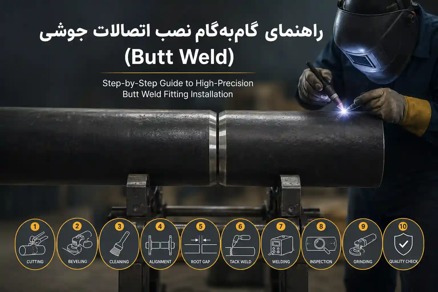
🔧 Step-by-Step Guide to Installing Butt Weld Fittings with High Precision
Complete reference for engineers, technicians, and inspectors based on ASME B16.9 standards
📑 Table of Contents
- 1. Introduction
- 2. What are Butt Weld Fittings?
- 3. Types of Butt Weld Fittings
- 4. Relevant International Standards
- 5. Pre-Installation Preparation
- 6. Required Tools
- 7. Fit-Up Procedure
- 8. Step-by-Step Welding Procedure
- 9. Common Installation Mistakes
- 10. Quality Control and Inspection
- 11. Safety Requirements
- 12. Field Best Practices
- 13. Maintenance and Repair
- 14. Frequently Asked Questions
- 15. Conclusion and References
1. Introduction
Butt weld fittings are among the most critical components in piping systems across the oil and gas, petrochemical, power generation, and process industries. These fittings are joined to pipes through full penetration welds, creating a joint with strength equal to or greater than the pipe itself. Unlike threaded or flanged connections, butt weld fittings have no mechanical joints, gaskets, or leak paths, making them ideal for high-pressure and high-temperature applications.
Proper installation of these fittings requires meticulous attention at every stage—from surface preparation and welding to final inspection. Any error can lead to localized stresses, reduced service life, or catastrophic system failure. This article serves as a comprehensive, step-by-step guide covering all engineering and execution aspects of installing butt weld fittings.
2. What are Butt Weld Fittings?
Butt weld fittings are components used to connect pipes, change flow direction, or alter pipe diameter in piping systems. In this method, the fitting's end is placed butt-to-butt against the pipe end, and a full-penetration girth weld is applied. This type of connection, due to its monolithic structure and absence of mechanical weak points, is the first choice for high-pressure transmission lines (such as oil and gas pipelines).
The final strength of a butt weld joint depends on weld quality, welder skill, and strict adherence to the Welding Procedure Specification (WPS). Standards like ASME B16.9 define dimensions, tolerances, and manufacturing requirements to ensure uniformity and compatibility.
3. Types of Butt Weld Fittings
ASME B16.9 covers various butt weld fittings, each with specific applications in piping systems:
| Fitting Type | Description | Primary Application |
|---|---|---|
| Elbow | Changes flow direction (45°, 90°). Available in Long Radius (LR) and Short Radius (SR) | Redirecting flow in pipelines |
| Tee | Creates a 90° branch. Available in Equal and Reducing types | Branching off from the main line |
| Reducer | Reduces or increases pipe diameter. Available in Concentric and Eccentric types | Connecting pipes of different diameters |
| Cap | Closes the end of a pipe | Sealing pipe ends |
| Stub End | Used with Lap Joint flanges | Systems requiring disassembly |
For detailed dimensions and specifications of each fitting type, refer to the dedicated elbow, tee, and reducer pages on Iran Etesal.
4. Relevant International Standards
Compliance with international standards is essential for quality and safety in butt weld fitting installation. Key standards include:
- ASME B16.9: Primary standard for dimensions, tolerances, and manufacturing requirements of butt weld fittings.
- ASME B31.3: Process Piping design and installation standard.
- ASME B31.8: Gas Transmission and Distribution Piping Systems.
- API 1104: Welding of Pipelines and Related Facilities.
- ASME Section IX: Welder and welding procedure qualification.
- ASTM A234 / A403: Material specifications for carbon and stainless steel fittings.
- MSS SP-75: High-diameter butt weld fittings (above 26 inches).
For complete details on ASME B16.9, visit its dedicated page on Iran Etesal.
5. Pre-Installation Preparation
Preparation is the foundation of a successful installation. Neglecting this stage is the most common cause of weld defects.
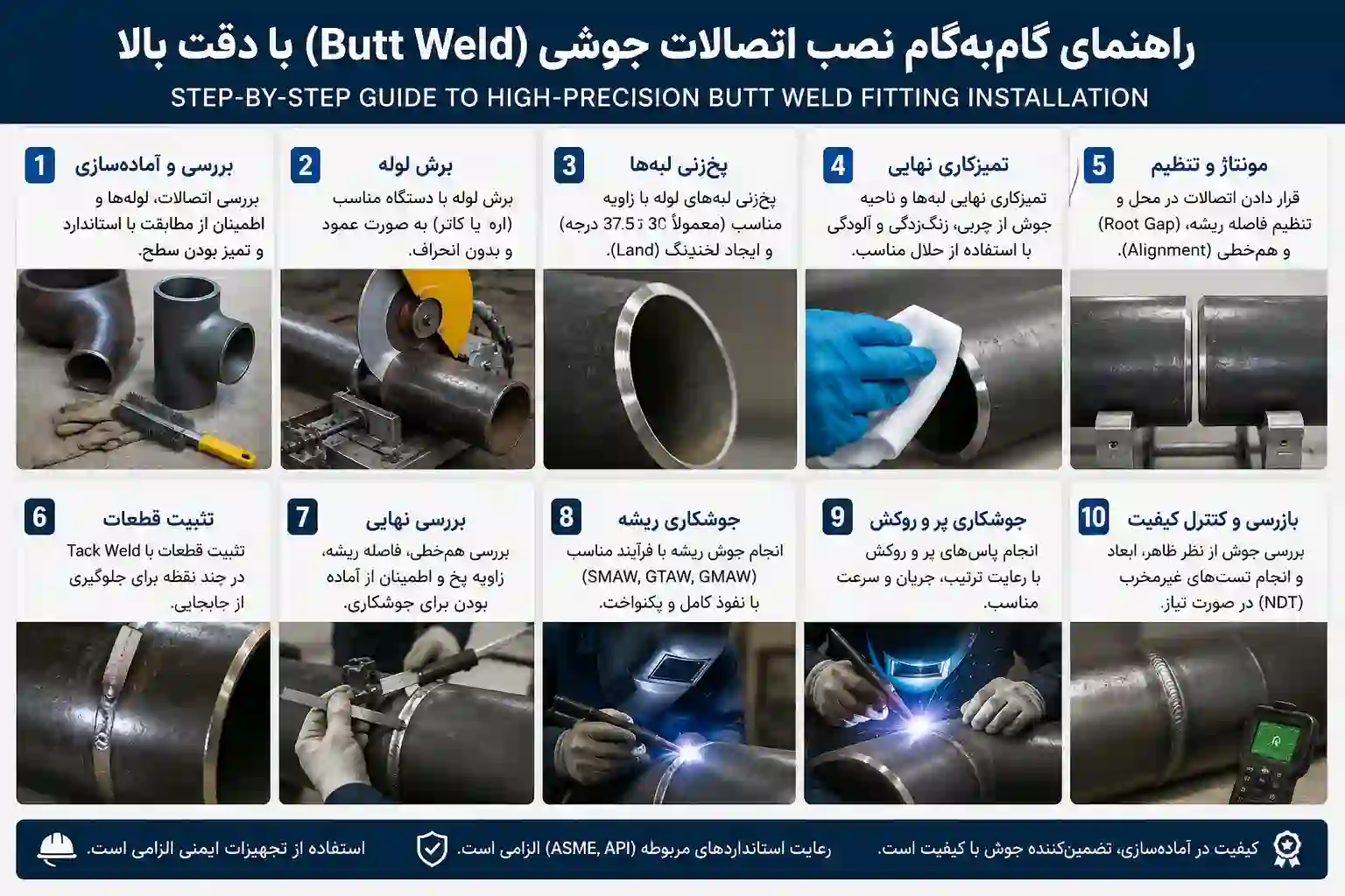
5-1. Receiving Inspection
- Visual Inspection: Check for cracks, dents, or surface defects.
- Standard Compliance: Verify marking (size, Schedule, material, heat number).
- Material Test Certificate (MTC): Ensure chemical composition and mechanical properties match specifications.
- Dimensional Inspection: Measure outside diameter, wall thickness, and key dimensions using calipers and gauges.
5-2. Surface and Edge Preparation
Pipe and fitting edges must be clean and free of all contaminants:
- Cleaning: Remove rust, oil, paint, moisture, and other contaminants using wire brushes, grinders, or suitable solvents.
- Beveling: Create a standard bevel angle (typically 30° to 37.5°) with a root face of about 1.5 mm to achieve full penetration.
- Square Cut: The pipe end must be cut perfectly perpendicular to its axis to ensure proper alignment.
📌 Technical Note: After beveling, prevent re-contamination of cleaned surfaces. Use appropriate cleaning agents like acetone if needed.
6. Required Tools
Using the right tools significantly improves installation accuracy and speed:
- Alignment Clamps: To hold and align components during tack welding.
- Spirit Level and Laser Level: To ensure horizontal and vertical alignment.
- Calipers and Gap Gauges: For precise measurement of root gap and dimensions.
- Pipe Stands: For safe and correct pipe positioning.
- Welding Machine: Selected based on the welding process (SMAW, GTAW, GMAW, SAW).
For accurate weight, dimension, and pressure calculations in piping projects, use the Iran Etesal Piping Engineering Tools.
7. Fit-Up Procedure
Fit-up is the process of positioning and aligning components before final welding. The quality of this stage directly impacts the final weld strength.
7-1. Positioning and Alignment
- Adjust components to be coaxial. Maximum misalignment (Hi-Lo) should not exceed 10% of wall thickness.
- Root Gap: Typically set between 1.5 to 3 mm, depending on thickness and welding process.
- Ensure uniform root gap around the entire circumference.
- Use internal alignment tools to prevent ovality in large-diameter pipes.
7-2. Tack Welding
Tack welds temporarily hold components during the main welding process:
- Number and size of tack welds depend on pipe diameter and thickness (typically 4 to 8 points, 10 to 20 mm long).
- Avoid large, heavy tack welds that could cause stress or cracking.
- When possible, use alignment clamps instead of tack welds to prevent initial distortion.
⚠️ Important Warning: Research shows that tack weld placement significantly influences final distortion and residual stresses in butt weld joints. Proper layout and execution are critical.
8. Step-by-Step Welding Procedure
The welding process must strictly follow the qualified Welding Procedure Specification (WPS).
8-1. Root Pass
The most critical pass, requiring full penetration to the root of the joint. Typically performed using GTAW (TIG) or SMAW with low-hydrogen electrodes.
- Use back purging when shielding gas is required to prevent oxidation.
- After completion, inspect the root pass for cracks or porosity.
8-2. Fill Passes
Subsequent passes to fill the weld groove after the root pass:
- Each pass should overlap the previous by about 30% to 50%.
- Slag must be completely removed between passes.
- Interpass temperature must be controlled to prevent excessive heat input.
8-3. Cap Pass
The final weld pass forming the surface. It must be smooth, free of undercut, and slightly above the pipe surface.
| Weld Stage | Objective | Key Points |
|---|---|---|
| Root | Full penetration | High precision, back purging (if needed) |
| Fill | Fill the groove | Slag cleaning, interpass temperature control |
| Cap | Complete the weld surface | Smooth finish, no undercut |
9. Common Installation Mistakes
- Improper Preparation: Incomplete cleaning or incorrect beveling.
- Incorrect Root Gap: Too small leads to incomplete penetration; too large causes porosity or burn-through.
- Misalignment (Hi-Lo): Creates localized stresses and reduces joint life.
- Incorrect Welding Parameters: Excessive or insufficient current and speed.
- Poor Tack Welds: Cracking or improper size.
- Ignoring PWHT: When required by standards.
10. Quality Control and Inspection
Inspection is essential to ensure weld quality.
10-1. Visual Inspection
- Check weld appearance (uniformity, height, width).
- Inspect for surface defects: cracks, porosity, undercut, and overlap.
10-2. Non-Destructive Testing (NDT)
| Test Method | Application |
|---|---|
| Penetrant Testing (PT) | Detects surface cracks and open defects |
| Magnetic Particle Testing (MT) | Detects surface and subsurface defects in magnetic steels |
| Ultrasonic Testing (UT) | Detects internal defects and measures thickness |
| Radiographic Testing (RT) | Detects internal defects using X-rays or gamma rays |
10-3. Pressure Testing (Hydrotest / Pneumatic)
Final system test performed at pressures above working pressure (typically 1.5x) to confirm the integrity of the entire system, including welds.
11. Safety Requirements
- Use complete PPE including welding helmet, gloves, and protective clothing.
- Provide adequate ventilation in the welding area.
- Keep flammable materials away from the welding zone.
- Obtain a Hot Work Permit in industrial environments.
- Follow safety protocols during pressure testing and establish safety zones.
12. Field Best Practices
- Cutting and Preparation: Always use sharp, appropriate cutting tools to prevent pipe deformation.
- Final Alignment: Recheck alignment before each weld pass.
- Adverse Weather Welding: Use preheating in cold conditions and windshields in windy conditions.
- Documentation: Record all steps, parameters, and inspection results.
13. Maintenance and Repair
- Periodic Inspection: Regularly inspect welds for corrosion, cracking, or deformation.
- Weld Repair: If defects are found, grind out the affected area and re-weld according to WPS.
- Corrosion Protection: Apply protective coatings to welds in corrosive environments.
14. Frequently Asked Questions (FAQ)
1. What is the difference between Long Radius and Short Radius elbows?
Long Radius (LR) elbows have a radius of curvature 1.5 times the pipe diameter, reducing pressure drop and are suitable for main lines. Short Radius (SR) elbows have a radius equal to the pipe diameter, used in tight spaces.
2. What is the ideal root gap for welding?
The root gap depends on pipe thickness and welding process, but typically ranges from 1.5 to 3 mm.
3. When is Post-Weld Heat Treatment (PWHT) required?
For alloy steels and high thicknesses (typically above 20 mm), and as required by design standards like ASME B31.3, PWHT is mandatory to reduce residual stresses.
4. What size range does ASME B16.9 cover?
This standard covers dimensions and tolerances for butt weld fittings from NPS ½" to NPS 48".
5. How can I ensure alignment during welding?
Use alignment clamps, proper tack welds, and recheck alignment before each pass.
6. What is the best welding process for the root pass?
GTAW (TIG) is generally the best choice for the root pass due to its precise heat and penetration control.
15. Conclusion and References
Precise installation of butt weld fittings is a multi-step, sensitive process requiring technical knowledge, practical skill, and strict adherence to standards. From surface preparation and fit-up to welding and final inspection, each stage plays a vital role in ensuring the strength, safety, and longevity of the piping system. By following the principles outlined in this guide and using quality materials and equipment, you can achieve the highest quality joints.
For further information on dimensions and technical specifications of various butt weld fittings, refer to the Iran Etesal product pages.
📚 References and Standards
- ASME B16.9: Factory-Made Wrought Buttwelding Fittings
- ASME B31.3: Process Piping
- ASME B31.8: Gas Transmission and Distribution Piping Systems
- API 1104: Welding of Pipelines and Related Facilities
- ASME Section IX: Welding and Brazing Qualifications
- ASTM A234 / A403: Standard Specification for Piping Fittings
- MSS SP-75: Specification for High-Test Wrought Buttwelding Fittings
- ISO 3183: Petroleum and natural gas industries — Steel pipe for pipeline transportation systems