
Residential Gas Piping Design: Layout Planning, Installation Principles, and Safety Requirements

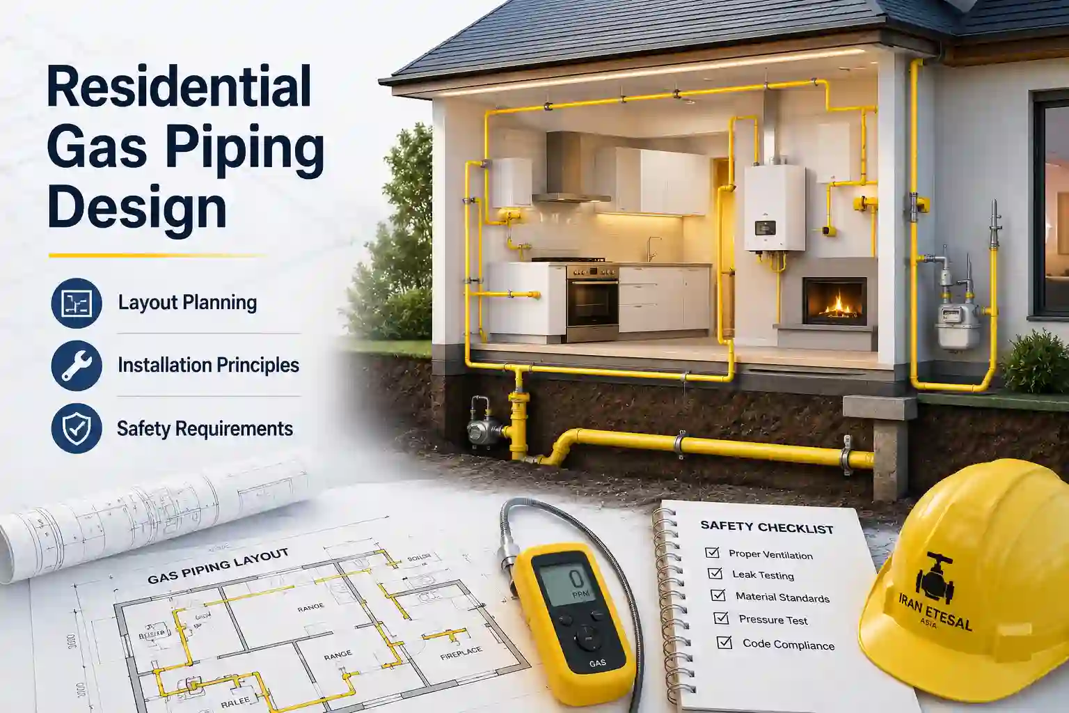
Residential Gas Piping Design: Layout Planning, Installation Principles, and Safety Requirements
Table of Contents
- Introduction to Residential Natural Gas Piping Systems
- 1. Importance of Proper Gas Piping Layout Design
- 2. Initial Planning and Building Assessment
- 3. Gas Pipe Routing Principles and Optimization
- 4. Pipe Sizing Considerations and Pressure Drop Management
- 5. Material Selection for Residential Gas Piping Systems
- 6. Indoor and Outdoor Gas Piping Installation Practices
- 7. Pipe Supports, Protection, and Accessibility Requirements
- 8. Safety Requirements and Risk Prevention
- 9. Inspection, Testing, and Commissioning Procedures
- 10. Common Design and Installation Mistakes
- 11. Maintenance and Long-Term Reliability
- 12. Conclusion
Introduction to Residential Natural Gas Piping Systems
Residential natural gas piping systems are the essential infrastructure that delivers fuel from the utility's point of delivery to the various gas appliances within a home. These systems include water heaters, furnaces, boilers, cooktops, ovens, fireplaces, and outdoor grills. The proper design and installation of these systems are paramount for ensuring the safety of occupants, the reliability of gas supply, and the efficient operation of appliances.
The design of a residential gas piping system must consider a multitude of factors. It must be sized correctly to meet the peak demand of all connected appliances, routed safely to avoid damage and interference with other building services, and constructed with approved materials and methods. The overarching goal is to create a system that is safe, durable, and capable of delivering gas at the correct pressure and volume to every appliance, under all expected operating conditions [citation:8].
This comprehensive guide provides an in-depth exploration of the core principles of residential gas piping design, drawing on internationally recognized standards such as the National Fuel Gas Code (NFPA 54/ANSI Z223.1), the International Fuel Gas Code (IFGC), and ASME B31.8. The information presented is intended for engineers, contractors, designers, and technical professionals seeking a detailed, standards-based reference on the subject [citation:2][citation:7][citation:11].
1. Importance of Proper Gas Piping Layout Design
The layout of a residential gas piping system is not merely an exercise in connecting points A to B; it is a critical engineering activity that profoundly influences the system's safety, efficiency, and long-term reliability.
1.1 Safety and Risk Mitigation
The most important objective of a well-designed gas piping layout is safety. A poorly designed system can lead to leaks, which pose significant risks of fire, explosion, and carbon monoxide poisoning. A design that minimizes joints, avoids vulnerable locations, and ensures proper venting and isolation directly contributes to a safer installation. The codes and standards governing gas piping are fundamentally safety-focused, aiming to reduce these risks to an acceptable level [citation:11].
1.2 System Reliability and Performance
A proper layout ensures that all appliances receive an adequate and stable gas supply. This is achieved through correct pipe sizing, minimizing pressure drops, and avoiding excessive system length. If the piping system is undersized or poorly routed, appliances may not function correctly, leading to poor performance, incomplete combustion, and increased emissions.
1.3 Economic Efficiency
An optimized layout minimizes the total length of piping and the number of fittings required, reducing material costs. It also lowers installation labor costs by simplifying runs and making them easier to install. Furthermore, a well-designed system prevents costly future repairs caused by corrosion, physical damage, or repeated failures from pressure problems.
1.4 Compliance with Codes and Standards
All gas piping installations must comply with local and national codes, such as the IFGC and NFPA 54 [citation:3]. A proper layout design is the first step in demonstrating compliance. It provides the basis for calculating pipe sizes, selecting appropriate materials, and following installation best practices that will satisfy the authority having jurisdiction (AHJ) [citation:8].
2. Initial Planning and Building Assessment
The design process for a residential gas piping system begins with a comprehensive assessment of the building and the project requirements.
2.1 Defining the Scope of Work
- New Installation vs. Modification: Determine whether this is a new system or an addition to an existing one. For modifications, the existing system's capacity must be verified to ensure it can handle the additional load [citation:8].
- Appliances: Identify all gas appliances to be served. Gather their specifications, including the maximum input rating in Btu/h (or kW) and the minimum and maximum gas supply pressure required for proper operation. If the input rating is unknown, it must be estimated based on manufacturer data or other sources, but final sizing must always be verified with the actual connected load [citation:3].
- Gas Type: Identify the type of gas (natural gas or propane). This is critical because the heating value and specific gravity of the gas directly affect pipe sizing calculations [citation:3][citation:8].
2.2 Building Assessment
- Point of Delivery (POD): Locate the point of delivery, which is typically the outlet of the gas meter for natural gas or the outlet of the service pressure regulator for propane. The code jurisdiction typically begins at this point [citation:12].
- Structural Elements: Assess the building's structure to identify potential obstacles, such as load-bearing walls, beams, and columns, that will affect pipe routing.
- Existing Systems: Identify the location of other building services, such as electrical wiring, plumbing, HVAC ducts, and fire protection systems, to prevent conflicts during installation.
- Accessibility: Consider the accessibility of piping for future maintenance. Piping in concealed spaces should be minimized, and access points should be provided where possible.
2.3 Determining System Demand
The total demand is the sum of the maximum input ratings of all appliances that could be operating simultaneously. The IFGC requires that the total connected hourly load be used as the basis for pipe sizing, assuming all appliances could be operating at full capacity at the same time. However, if a diversity of load can be established, pipe sizing is permitted to be based on such loads [citation:8].
3. Gas Pipe Routing Principles and Optimization
Once the system demand is known, the next step is to plan the most effective path for the piping.
3.1 Routing Principles
- Minimize Length: The piping should be routed along the shortest possible path between the point of delivery and the appliances to minimize pressure drop and material cost.
- Minimize Fittings: Every fitting (elbow, tee, union) adds resistance and increases pressure loss. Therefore, the layout should minimize the number of fittings.
- Avoid Obstacles: Plan the route to avoid structural elements and other building services. This reduces installation difficulty and the risk of future damage.
- Identify the Longest Run: The most remote outlet (in terms of total developed length) will generally determine the allowable pressure drop for the entire system. This run is a critical input for pipe sizing calculations [citation:3][citation:8].
3.2 Optimization Strategies
- Branch Layout: In the common branch layout, a single main pipe (the trunk) runs from the meter to an area, with branches (laterals) connecting to individual appliances. This is an efficient design for residential systems.
- Manifold Layout: A manifold is a central distribution point where each appliance has its own dedicated pipe run. This can be advantageous when long individual runs are required, but it increases the total pipe length.
- Reduce Fitting Use: Long radius elbows create less turbulence and pressure loss than standard elbows. Strategic use of flexible connectors or corrugated stainless steel tubing (CSST) can sometimes reduce the number of fittings.
- Thermal Stress Management: The design must accommodate thermal expansion and contraction, especially in exposed or long runs. Rigid systems can be designed using optimization techniques to reduce weight and manage thermally induced stresses [citation:6][citation:15].
4. Pipe Sizing Considerations and Pressure Drop Management
Pipe sizing is the most critical technical task in gas piping design. The goal is to ensure that the pressure at each appliance inlet is never less than the manufacturer's minimum requirement when all appliances are operating at full capacity.
4.1 Gas Demand and Pressure Drop
The volumetric flow rate of gas required (CFH or m³/h) is determined by the sum of the maximum input ratings of the appliances [citation:3][citation:8].
The design pressure drop must be carefully calculated. The allowable pressure drop is the difference between the supply pressure (at the point of delivery) and the minimum pressure required at the appliance. It is usually limited to prevent excessive velocity in the piping system, which can cause noise and erosion [citation:1].
4.2 Sizing Methods
The IFGC provides two primary methods for sizing gas piping systems [citation:3]:
- Longest Length Method: This is the most common and conservative method. The pipe size for every section of the piping system is determined using the longest length from the point of delivery to the most remote outlet. This ensures that even the farthest outlet receives adequate gas pressure.
- Branch Length Method: This is a less conservative method. The pipe size of each section of the longest run is determined using the longest run length. However, the pipe size of all other branches is determined using the length from the point of delivery to the most remote outlet on that specific branch. This can result in smaller pipe sizes for some sections.
4.3 Sizing Procedure (Longest Length Method)
- Step 1: Determine the longest pipe run from the point of delivery to the most remote gas outlet [citation:3].
- Step 2: Determine the maximum gas demand (CFH) for each appliance and the total system load.
- Step 3: Select the appropriate sizing table from the IFGC based on the pipe material (e.g., steel, copper, CSST), gas type, inlet pressure, and allowable pressure drop [citation:3][citation:8].
- Step 4: In the chosen table, select the row that equals or exceeds the longest pipe length.
- Step 5: For each section of pipe, calculate the gas demand for all appliances supplied through that section. Then, find the column in the chosen table row that equals or exceeds this demand. The required pipe size is found at the top of that column [citation:3].
5. Material Selection for Residential Gas Piping Systems
Choosing the right piping material is essential for system longevity and safety. The selection is governed by building codes and must be suitable for the application.
| Material | Typical Applications | Key Standards | Notes |
|---|---|---|---|
| Black Steel Pipe | Indoor and outdoor above-ground systems | ASTM A53, ASME B36.10M | Traditional material; must be protected from corrosion below grade [citation:5][citation:12] |
| Galvanized Steel Pipe | Above-ground systems where additional corrosion protection is desired | ASTM A53 | Not recognized as adequate corrosion protection for underground use [citation:10][citation:12] |
| Corrugated Stainless Steel Tubing (CSST) | Indoor and outdoor above-ground and buried systems | ANSI LC 1/CSA 6.26 | Flexible; requires specific bonding and grounding. Pre-sleeved CSST is available for direct burial [citation:3][citation:12] |
| Copper Tubing | Indoor and outdoor above-ground systems | ASTM B837 | Must be of a type approved for fuel gas service |
| Polyethylene (PE) Pipe | Underground piping only | ASTM D2513 | Not approved for above-ground use. Requires tracer wire for locating [citation:12] |
For detailed dimensions and weights of pipe materials, refer to technical resources such as ASME B36.19 and ASTM A53 pipe sizes and weights.
6. Indoor and Outdoor Gas Piping Installation Practices
Installation practices differ significantly between indoor and outdoor environments, with each presenting unique challenges.
6.1 Indoor Piping
- Piping must be routed and supported to prevent physical damage.
- Piping in concealed spaces (inside walls, floors, or ceilings) must be protected and installed in a manner that prevents leaks.
- Piping must be installed with clearances from heat sources and electrical components.
- Each appliance must have an accessible shut-off valve.
6.2 Outdoor and Underground Piping
- Corrosion Protection: Underground metallic piping must be protected from corrosion. This can be achieved through use of corrosion-resistant material (like PE), factory-applied insulating coatings, or a cathodic protection system. Galvanizing is not considered adequate protection below grade [citation:12].
- Burial Depth: The minimum burial depth is typically 12 inches (305 mm) for underground piping, though this may be reduced to 8 inches for supply lines to outdoor appliances in approved locations not subject to physical damage [citation:12].
- Penetrations: Gas piping is not permitted to penetrate a building's foundation wall below grade. The annular space between the pipe and the wall must be sealed when penetrating above grade [citation:12].
- Tracer Wire: A yellow-insulated copper tracer wire (18 AWG or larger) must be installed adjacent to underground non-metallic piping to allow for locating [citation:12].
- Plastic Pipe Limitations: Plastic pipe is not permitted within or under any building slab or to be operated at pressures greater than 100 psig (689 kPa) for natural gas [citation:12].
7. Pipe Supports, Protection, and Accessibility Requirements
Proper support and protection are essential for maintaining the integrity of the gas piping system.
7.1 Pipe Supports
Piping must be securely supported to prevent sagging, stress on joints, and potential damage. The spacing of supports is determined by the pipe material and size. Typical residential piping should be supported at intervals not exceeding 10 feet (3,048 mm) for steel pipe and 6 feet for copper or CSST. Straps, hangers, and clamps must be of the correct size and type for the material.
7.2 Protection
- Mechanical Protection: Where piping is subject to physical damage (e.g., in garages, near driveways), it must be protected by a guard rail or be buried at sufficient depth [citation:12].
- Corrosion Protection: As noted, underground metallic piping requires specific corrosion protection methods.
- Heat and Fire Protection: Piping must be kept at a safe distance from heat-producing appliances and other high-temperature sources.
7.3 Accessibility
All shut-off valves, regulators, and other control devices must be readily accessible. Piping should be routed to allow for future maintenance and inspection. Concealed piping should be avoided, and access panels should be provided when necessary [citation:8].
8. Safety Requirements and Risk Prevention
Safety is the paramount concern in gas piping design, guided by codes like NFPA 54, which are developed by the National Fire Protection Association to mitigate hazards from fire, explosion, and carbon monoxide [citation:11].
8.1 Ventilation
Proper ventilation and combustion air must be provided for all gas appliances to ensure complete combustion and prevent the buildup of carbon monoxide.
8.2 Gas Detection
Installation of carbon monoxide and combustible gas detectors in residential settings is a critical safety measure.
8.3 Soil Movement and External Hazards
Designers must consider external factors that can affect buried pipelines, such as soil movement (earthquakes, subsidence, landslides) and water currents, which can impose inertial loads on the pipe [citation:4].
8.4 Bonding and Grounding
All gas piping systems, particularly CSST, must be properly bonded and grounded to prevent electrical shocks and reduce the risk of damage from lightning strikes [citation:3].
8.5 Leak Prevention
Leak prevention is achieved through correct material selection, proper joint assembly, and mandatory leak testing. The risk of fire and explosion from gas leaks makes this a primary code objective [citation:11].
9. Inspection, Testing, and Commissioning Procedures
Once the piping is installed, it must be inspected and tested before being placed into service.
9.1 Inspection
- Material Verification: Ensure the installed materials match the design specifications.
- Visual Inspection: Check for proper support, clearances, and correct installation practices.
- Marking and Labeling: Verify that piping is properly labeled as "Gas" at regular intervals [citation:8].
9.2 Testing for Gas Tightness (Leak Testing)
This is a critical step to ensure no gas leakage occurs. A pressure test is performed using air or inert gas. The test procedure must specify the pipe volume, operating pressure, test pressure, test duration, and the test instrument used, which must be suitable for the pressure and volume being tested [citation:1].
- Air Test: The system is pressurized with air and monitored for any pressure drop, which would indicate a leak.
- Soap Bubble Test: A soapy water solution is applied to all joints and connections to detect leaks. This is a final check after the system has been purged and is ready for service.
9.3 Purging
After testing, the piping system must be purged of air or inert gas before it is filled with fuel gas. This is typically done by introducing fuel gas at a specific point and venting the air at another. The purge volume and safe outlet location must be considered [citation:1].
9.4 Commissioning
Commissioning involves verifying that the system operates as designed. This includes checking the gas pressure at each appliance and confirming that all control devices (regulators, overpressure shutoff valves) are set correctly [citation:1].
10. Common Design and Installation Mistakes
Avoiding common pitfalls is key to a successful installation.
- Undersizing Piping: This is the most frequent error, leading to low gas pressure at appliances, poor performance, and potential safety hazards.
- Incorrect Pipe Sizing Method: Failing to use the correct design method (Longest Length vs. Branch Length) or not accounting for all appliances in a section can result in an undersized system [citation:3].
- Inadequate Corrosion Protection: Especially for underground metallic piping, not providing proper protection (coating or cathodic protection) will lead to rapid pipe failure [citation:12].
- Ignoring Thermal Expansion: Not accommodating the thermal expansion and contraction of piping can lead to stress fractures and leaks [citation:6][citation:15].
- Poor Support: Insufficient or improper pipe supports can cause sagging, stress on joints, and potential leaks.
- Inadequate Testing: Not performing a proper pressure test, or testing at the wrong pressure, is a major safety violation.
- Mixing Materials: Using incompatible materials or fittings can lead to galvanic corrosion and joint failure.
- Failing to Verify Sizing with Connected Load: Relying on estimated values for appliance input without verifying the actual load can result in an incorrectly sized system [citation:3].
- Insufficient Clearance: Running gas piping too close to heat sources, electrical panels, or other hazards.
11. Maintenance and Long-Term Reliability
To ensure the long-term safety and reliability of a gas piping system, a proactive maintenance plan is essential.
- Periodic Visual Inspections: Conduct regular inspections of accessible piping, looking for signs of corrosion, physical damage, or loose supports.
- Leak Detection: Be aware of the smell of gas and use soap bubble tests periodically on joints, especially after any seismic activity or significant ground movement.
- Regulator and Valve Checks: Test shut-off valves and regulators to ensure they function correctly.
- Corrosion Monitoring: If cathodic protection is used, it must be monitored and maintained in accordance with an approved program [citation:12].
- Tracer Wire Maintenance: Ensure tracer wires for underground plastic piping are accessible and functional for future locating.
- Record Keeping: Keep a detailed record of the system's design, including as-built drawings, material specifications, and all test results for future reference.
12. Conclusion
The design and installation of residential gas piping systems is a discipline that demands a rigorous, standards-based approach. From the initial planning and load calculation to the final inspection and testing, every step is governed by codes that prioritize safety and reliability. By adhering to the principles outlined in this guide—understanding system demand, optimizing pipe routing, correctly sizing the piping, selecting appropriate materials, and following proven installation practices—engineers, designers, and contractors can ensure the creation of gas systems that are safe, efficient, and durable.
This article has provided a comprehensive overview of these principles, drawing on key international standards such as NFPA 54, the IFGC, and ASME B31.8. The information presented serves as a foundation for sound engineering judgment and is intended to help professionals deliver installations that protect lives, property, and the environment for decades to come.
Selection & Engineering LR vs SR Elbow 45 vs 90 Elbow Seamless vs Welded SCH 40 vs SCH 80 Butt Weld vs Socket Weld
Quality, Manufacturing & Market Manufacturing Process Elbow Manufacturing Detect Fake Fittings Global Steel Market Market Analysis
Procurement & Maintenance Procurement Guide Leak Case Study Maintenance & Repair Piping Tools
Products Elbows Tees Reducers Caps Pipe Nipples Product List Multi-Products
Knowledge Base Pipes Pipe Fittings Pipe Manufacturing NPS & Schedule Pipe Beveling Butt Weld Fittings Knowledge
Need High-Quality Piping Components or Expert Support?
Iran Etesal — ASME B16.9 certified, carbon & stainless steel butt weld fittings for gas, petrochemical, and power projects. Global export and engineering support.
Residential Gas Piping – Frequently Asked Questions
The most critical factor is ensuring the system is sized correctly to deliver adequate gas pressure and volume to all connected appliances under maximum simultaneous demand. This directly impacts safety, appliance performance, and compliance with codes like NFPA 54 and the IFGC. Proper sizing prevents issues such as low flame output, incomplete combustion, and carbon monoxide production.
NFPA 54, IFGCThe primary standards are the National Fuel Gas Code (NFPA 54/ANSI Z223.1) and the International Fuel Gas Code (IFGC). These codes are adopted by most local jurisdictions and provide comprehensive requirements for design, installation, inspection, and testing of gas piping systems.
NFPA 54, IFGCCommonly approved materials include: Black steel pipe (ASTM A53), Corrugated Stainless Steel Tubing (CSST), Copper tubing (ASTM B837), and Polyethylene (PE) pipe (ASTM D2513) for underground use only. Each material has specific joining methods and installation requirements defined by the applicable codes.
Pipe sizing is determined using the Longest Length Method or the Branch Length Method as defined by the IFGC. The process involves: (1) calculating the total gas demand (Btu/h) of all appliances, (2) measuring the longest run from the meter to the most remote appliance, (3) selecting the appropriate sizing table based on material, gas type, inlet pressure, and allowable pressure drop, and (4) matching the demand to the correct pipe size in the table.
IFGC Chapter 4The Longest Length Method sizes every section of pipe based on the total length of the longest run from the meter to the most remote outlet. It is more conservative. The Branch Length Method sizes each branch based on the length from the meter to the most remote outlet on that specific branch, which can result in smaller pipe sizes for some sections.
IFGC Chapter 4No. Galvanized steel pipe is not recognized as providing adequate corrosion protection for underground use. Underground metallic piping must be protected with factory-applied insulating coatings, cathodic protection, or be constructed of corrosion-resistant materials like polyethylene.
NFPA 54, IFGCThe minimum burial depth is typically 12 inches (305 mm) for underground piping. However, this may be reduced to 8 inches for supply lines to outdoor appliances in approved locations that are not subject to physical damage.
IFGC Chapter 4A tracer wire is a yellow-insulated copper wire (18 AWG or larger) that must be installed adjacent to underground non-metallic piping. It allows the pipe to be located in the future using electronic locating equipment, preventing accidental damage during excavation.
IFGC Chapter 4Yes, CSST can be used for outdoor and underground installations, provided it is specifically listed for that use. Pre-sleeved CSST is available for direct burial applications. All CSST installations require proper bonding and grounding per manufacturer instructions and code requirements.
ANSI LC 1, NFPA 54Leak testing is performed using air or inert gas. The test pressure must be at least 1.5 times the operating pressure, but not less than 3 psig (20.7 kPa) for systems operating at 0.5 psig or less. The system must hold pressure for a specified duration without any pressure drop, indicating a leak.
NFPA 54, IFGCRegular visual inspections should be conducted annually or whenever the system is disturbed. The system should also be inspected after any seismic activity or significant ground movement. At a minimum, all accessible piping should be checked for corrosion, physical damage, and loose supports.
Common signs include: low flame output on cooktops, yellow or flickering flames (incomplete combustion), slow recovery times on water heaters, difficulty maintaining temperature in furnaces, and sooting on appliances. All these indicate that the appliances are not receiving adequate gas flow.
Work on gas piping systems must be performed by qualified, licensed professionals in accordance with all applicable codes and regulations. Improper installation can lead to severe injury, death, and property damage. Always check with your local authority having jurisdiction (AHJ) for specific requirements.
Natural gas and propane have different heating values and specific gravities, which affect pipe sizing calculations. Propane is typically supplied at higher pressures and has a higher heating value per cubic foot. All sizing tables in the IFGC and NFPA 54 are specific to the gas type, so the correct table must be used.
No. Polyethylene (PE) pipe is not approved for above-ground use. It is permitted only for underground applications. All piping inside buildings must be of metallic materials or CSST, as specified by the applicable codes.
IFGC Chapter 4, NFPA 54The allowable pressure drop is typically limited to 0.5 inches of water column (in w.c.) for systems operating at 7 to 14 in w.c. However, the exact allowable drop depends on the inlet pressure and the minimum pressure required by the appliances. The designer must ensure the pressure at every appliance inlet never falls below the manufacturer's minimum requirement.
The gas demand is typically the maximum input rating (Btu/h) of the appliance, which is found on the appliance data plate or in the manufacturer's specifications. If the rating is not available, it must be estimated based on similar appliances, but final sizing must always be verified with the actual connected load.
Yes, but the pipe must be protected from physical damage. It must be sleeved with a metallic sleeve when passing through masonry or concrete walls. The annular space between the pipe and the sleeve must be sealed with an approved fire-stop material. Additionally, the pipe must be properly supported on both sides of the penetration.
IFGC Chapter 4Each gas appliance must have an accessible shut-off valve installed in the same room as the appliance, within 6 feet (1.8 m) of the appliance. This valve allows the appliance to be isolated for servicing, maintenance, or in an emergency without shutting off the entire gas supply to the building.
IFGC Chapter 4Proper bonding and grounding must be performed by a qualified electrician or technician. CSST systems require specific bonding techniques per manufacturer instructions. The gas piping system must be bonded to the electrical service grounding electrode system. This reduces the risk of electrical shock and damage from lightning strikes.
NFPA 54, NECA sediment trap is a short length of pipe installed at a low point in the system, typically before each appliance. Its purpose is to collect any debris, moisture, or sediment that may be carried in the gas stream, preventing these contaminants from entering and damaging the appliance controls or burners.
IFGC Chapter 4, NFPA 54Flexible gas connectors are permitted for connecting appliances, but they must be listed for the application. The connector length is typically limited to 6 feet for residential appliances. The connector must not be concealed within the appliance or pass through walls, floors, or ceilings.
IFGC Chapter 4