
Inspection and Quality Control During Butt Weld Pipe Fittings Installation: Standards, Inspection Procedures, NDT, and Engineering Best Practices
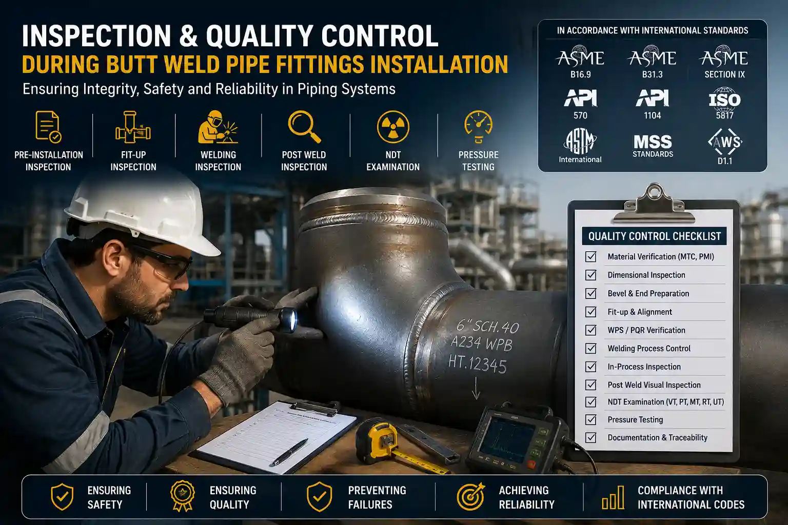
Inspection and Quality Control During Butt Weld Pipe Fittings Installation
1. Introduction
The installation of butt weld pipe fittings represents one of the most critical phases in the construction of industrial piping systems. The integrity of these welded connections directly influences the safety, reliability, and operational longevity of facilities across the oil and gas, petrochemical, power generation, and process industries. Unlike threaded or flanged connections, butt welds create a permanent, metallurgical bond that becomes an integral part of the pressure-containing system. Any defect introduced during installation can lead to catastrophic failure, environmental damage, and significant financial losses.
This article provides a comprehensive technical guide to the inspection and quality control procedures required during the installation of butt weld pipe fittings. It is intended for mechanical engineers, piping engineers, QA/QC inspectors, EPC contractors, and construction managers. The guidance is based on internationally recognized codes and standards, including ASME B16.9, ASME B31.3, ASME Section IX, API 570, and others, ensuring alignment with industry best practices.
For a deeper understanding of the impact of ASME B16.9 on the industry, refer to our detailed analysis.
2. Why Inspection Matters During Butt Weld Pipe Fittings Installation
Butt weld fittings are designed to withstand high pressures, extreme temperatures, and corrosive environments. The welding process, if not properly controlled, can introduce a range of defects that compromise the mechanical properties of the joint. These defects include lack of fusion, porosity, cracks, undercut, and excessive reinforcement, each of which can serve as a stress concentration point and initiation site for failure.
Inspection during installation is not merely a regulatory requirement; it is an essential engineering practice that serves multiple purposes:
- Verification of Compliance: Ensures that all work conforms to the applicable codes, standards, and project specifications.
- Defect Prevention: Identifies potential issues during fit-up and welding, allowing for corrective action before a defect is embedded in the final joint.
- Quality Assurance: Provides documented evidence that the installation meets the required quality standards, supporting the final handover and regulatory approval.
- Lifecycle Performance: A properly inspected and installed fitting will have a longer service life, requiring less maintenance and reducing the risk of unplanned downtime.
For further insights into welding integrity, refer to our welded joint leak case study.
3. Applicable International Standards
The inspection and quality control of butt weld pipe fittings installation are governed by a comprehensive set of international standards. These standards provide the framework for material verification, welding procedures, inspection methods, and acceptance criteria. Understanding these standards is fundamental for any engineer or inspector involved in piping installation.
| Standard | Scope and Application |
|---|---|
| ASME B16.9 | Defines the dimensional requirements for factory-made wrought buttwelding fittings. It is the primary standard for the fittings themselves, specifying dimensions, tolerances, and marking. |
| ASME B31.3 | The Process Piping Code. It provides the design, fabrication, inspection, and testing requirements for piping systems in industrial facilities. It is the overarching code for most process plant piping. |
| ASME Section IX | Covers welding, brazing, and fusing qualifications. It specifies the requirements for welding procedure specifications (WPS) and welder performance qualifications (WPQ), ensuring that welding is performed by qualified personnel using qualified procedures. |
| ASME B16.25 | Specifies the bevel preparation for buttwelding ends. It is critical for ensuring that the fitting's bevel is prepared correctly for the welding process, affecting fit-up and weld penetration. |
| API 570 | The Piping Inspection Code. It provides guidelines for the inspection, rating, repair, and alteration of in-service piping systems. While primarily for post-construction, its principles are relevant to ensuring long-term integrity. |
| API 1104 | Welding of Pipelines and Related Facilities. This is the primary standard for welding on cross-country pipelines and related facilities, often used in conjunction with ASME B31.4 or B31.8. |
| ISO 5817 | Provides quality levels for imperfections in fusion welded joints. It is often referenced in European projects and provides a framework for classifying weld imperfections. |
Inspection personnel must be familiar with the specific edition of each standard required by the project. The latest editions should be used whenever possible.
For more on the differences between butt weld and socket weld in high-pressure applications, see our dedicated comparison guide.
4. Pre-installation Inspection
Pre-installation inspection is the first line of defense against defects. This phase ensures that the materials, including the fittings, pipe, and consumables, are fit for purpose before any welding begins. Proper pre-installation inspection can prevent costly rework and delays later in the project.
4.1 Material Verification
Material verification is essential to confirm that the correct materials are used for the intended service. The consequences of using the wrong material can be catastrophic, leading to premature failure due to corrosion, embrittlement, or inadequate strength.
- Mill Test Certificate (MTC) Review: Every shipment of fittings and pipe should be accompanied by an MTC. This document provides the chemical composition and mechanical properties of the material. Inspectors must verify that the MTC matches the purchase order and the material markings. The certificate should include heat numbers, which are critical for traceability.
- Positive Material Identification (PMI): PMI is a non-destructive method used to verify the elemental composition of the material. Portable spectrometers are used to confirm the alloy grade, such as confirming that a fitting is indeed ASTM A234 WPB or ASTM A403 WP316. PMI is particularly critical for alloy and stainless steels where a mix-up can have severe consequences.
- Heat Number Verification: Each piece of material should have a heat number stamped or stenciled on it. The inspector must trace this heat number back to the MTC to ensure a complete chain of traceability. This is vital for quality assurance and for any future failure analysis.
4.2 Storage and Handling Inspection
- Storage Inspection: Fittings should be stored off the ground on racks or pallets to prevent contamination by dirt, moisture, or other ground-level debris. They should be protected from the elements, especially if they are made of carbon steel, to prevent rusting.
- Transportation Damage: Inspect all fittings for damage that may have occurred during shipping. Look for dents, gouges, or any other mechanical damage that could compromise the fitting's integrity or affect fit-up. Check the bevels for nicks or damage that would affect welding.
4.3 Visual and Dimensional Inspection
- Surface Defects: Visually inspect the fitting for cracks, laminations, seams, or other surface discontinuities. These are unacceptable and would require the fitting to be rejected. Ensure the surface is clean and free from excessive rust, mill scale, or other coatings that could interfere with welding.
- Dimensional Inspection: Verify the key dimensions of the fitting. This includes:
- Outside Diameter (OD): Must be within the tolerances specified in ASME B16.9 or the relevant standard to ensure a proper fit with the pipe.
- Wall Thickness: Should be checked to ensure it meets the minimum requirements. Wall thickness can be measured using ultrasonic gauges.
- Center-to-End Dimensions: This is critical for ensuring that the fitting will fit correctly in the piping layout. Dimensions should match the engineering drawings and the requirements of ASME B16.9. For specific dimensions of elbows and tees, refer to our dimension tables.
- Bevel and End Preparation Inspection:
- Bevel Angle and Root Face: Inspect the bevel angle, root face, and land to ensure they conform to the requirements of ASME B16.25 and the welding procedure. Incorrect bevel preparation can lead to incomplete fusion or inadequate penetration.
- End Preparation: The inside and outside of the fitting ends must be clean and free from burrs, sharp edges, or other defects that could affect fit-up or welding.
4.4 Traceability and Documentation Review
All inspection findings must be documented. This includes creating a comprehensive record of all material certifications, PMI results, and dimensional checks. The documentation should be organized and made readily available for review by the client, regulatory authorities, or other stakeholders. This traceability is essential for quality control and for addressing any future issues that may arise.
For information on detecting fake welding fittings, refer to our dedicated guide.
5. Fit-up Inspection
Fit-up is the process of aligning and preparing the pipe ends and fitting before welding. The quality of the fit-up has a direct impact on the quality of the weld and the integrity of the joint.
5.1 Alignment and Root Gap
- Alignment: The pipe ends and fitting must be properly aligned. The centerlines should be within the tolerances specified in the applicable code, typically 1/16" for most sizes. Misalignment, often referred to as "hi-low," creates a stress concentration and makes welding difficult.
- Root Gap: The root gap is the space between the pipe ends. It must be set correctly per the WPS to allow for proper penetration of the root pass. If the gap is too small, the weld may not penetrate fully. If it is too large, there is a risk of burn-through or excessive reinforcement.
5.2 Tack Weld and Joint Cleanliness Inspection
- Tack Weld Inspection: Tack welds should be inspected for cracks or other defects. They should be placed uniformly around the joint and be of sufficient quality to hold the alignment during the main welding process. Tack welds must be ground out if they are of poor quality or if they will interfere with the root pass. The material used for tack welding must be consistent with the main weld material.
- Joint Cleanliness: The joint area, both inside and outside, must be clean. Oil, grease, dirt, rust, paint, or any other contaminant must be removed by grinding or with appropriate solvents. Contaminants can cause porosity and other weld defects.
For guidance on selecting the right elbow angle during design, review our selection guide.
6. Inspection During Welding
Inspection during welding is a proactive measure to ensure the process is performed correctly. It is not sufficient to simply inspect the final weld; the conditions and procedures used to create it must also be verified.
6.1 Welding Procedure and Personnel Verification
- WPS and PQR Verification: The Welding Procedure Specification (WPS) must be available at the worksite. The inspector must verify that the WPS is approved for the materials, joint design, and thickness being welded. The Procedure Qualification Record (PQR), which documents the testing of the WPS, must also be available.
- Welder Qualification: Each welder must be qualified for the WPS they are using, per the requirements of ASME Section IX or the relevant standard. The inspector must check the welder's qualification cards to ensure they are valid and cover the required scope of work.
6.2 Welding Process and Environmental Controls
- Preheat: Preheat is required for many materials, especially carbon and alloy steels, to prevent cracking. The inspector must verify the preheat temperature has been reached and is maintained during welding. Temperature can be measured using temperature-indicating crayons, thermocouples, or infrared thermometers.
- Interpass Temperature: The interpass temperature is the temperature of the weld area between welding passes. It must be controlled to ensure the proper metallurgical structure. The inspector should monitor and record interpass temperatures.
- Environmental Conditions: Welding should not be performed in rain, snow, or high winds unless adequate protection is provided. Ambient temperature and humidity can also affect weld quality. The WPS will specify any limitations. For instance, welding should not be performed when the ambient temperature is below the specified minimum.
6.3 In-Process Visual Inspection
- Interpass Cleaning and Visual Check: After each pass, the weld surface should be cleaned of slag, spatter, and other debris. The inspector should visually check each pass for defects such as cracks or porosity before the next pass is deposited. This is a critical step to prevent defects from being buried in subsequent passes.
- Root Pass Inspection: The root pass is the most critical pass as it forms the base of the weld. It should be inspected for complete penetration, fusion, and freedom from defects. If defects are found, they must be ground out and repaired before continuing.
For more on seamless vs welded elbows and their manufacturing methods, see our detailed guide.
7. Post Weld Inspection
Once the welding is complete, a thorough post-weld inspection is required to verify the integrity of the joint and confirm it meets the acceptance criteria of the applicable standards.
7.1 Visual Inspection (VT)
- Surface Inspection: The weld and the adjacent base metal (about 1 inch on each side) must be visually examined. The surface must be clean and free of slag, spatter, and any other contaminants that would impede inspection.
- Weld Profile and Geometry: The weld should have a smooth and uniform profile. The reinforcement should be within acceptable limits. Excessive reinforcement can cause stress concentration. The weld shall be free from undercut, overlap, cracks, porosity, and incomplete fusion.
- Dimensional Verification: Post-weld, the inspector should verify that the completed joint has not distorted. If distortion has occurred, it may need to be corrected or may indicate a larger issue with the fit-up or welding sequence.
7.2 Weld Cleaning and Finishing
Proper cleaning is a prerequisite for effective inspection. All welds must be cleaned of slag, spatter, and any other debris. If a weld is to be ground or dressed, the resulting surface must be smooth and free of sharp notches. The appearance of the weld is often the first indication of quality.
7.3 Repair Requirements
If a weld is found to have defects that exceed the acceptance criteria, it must be repaired. The repair procedure must be qualified in accordance with the applicable code. The area of the repair must be ground out to sound metal, and the weld re-deposited. After repair, the weld must be re-inspected using the same methods as the original inspection.
8. Non-Destructive Examination (NDE/NDT)
Non-destructive examination (NDE) or non-destructive testing (NDT) refers to the methods used to evaluate the integrity of the weld and base material without damaging it. The choice of method depends on the type of defect being sought, the material, the joint configuration, and the code requirements.
| NDT Method | Purpose | Advantages | Limitations |
|---|---|---|---|
| Visual Testing (VT) | Detect surface defects and check weld profile | Simple, low-cost, immediate results | Only detects surface defects |
| Liquid Penetrant (PT) | Detect surface-breaking defects (cracks, porosity) | Portable, sensitive, works on all non-porous materials | Surface must be clean; detects only surface defects |
| Magnetic Particle (MT) | Detect surface and slight subsurface defects in ferromagnetic materials | Portable, sensitive, fast | Limited to ferromagnetic materials |
| Radiographic Testing (RT) | Detect volumetric defects (porosity, slag, lack of penetration) | Permanent record, good for volumetric defects | Radiation hazard, time-consuming, planar defects may be missed |
| Ultrasonic Testing (UT) | Detect internal and surface defects, measure wall thickness | Sensitive, immediate results, good for planar defects | Requires skilled operator, requires couplant |
For more on inspection, see our guide on detecting fake welding fittings.
9. Pressure Testing
Pressure testing is the final and most critical test to verify the integrity of the assembled piping system. It confirms that the system is capable of withstanding its design pressure without leaking.
9.1 Hydrostatic and Pneumatic Testing
- Hydrostatic Testing: This is the most common form of pressure testing. It involves filling the system with water and pressurizing it to a specified test pressure, typically 1.5 times the design pressure. Hydrostatic testing is preferred because water is relatively incompressible and contains a large amount of stored energy, making it safer than pneumatic testing in the event of a failure.
- Pneumatic Testing: Pneumatic testing uses air or an inert gas as the test medium. It is used when the system cannot be filled with water, for example, if it must be kept dry. Pneumatic testing is considered more hazardous due to the stored energy in compressed gas and requires more stringent safety precautions.
9.2 Preparation, Safety, and Inspection
- Preparation: All joints must be left unwrapped to allow for visual inspection during the test. The system must be properly vented to remove air (for hydrotest) or to allow for pressure relief. Blind flanges or caps may be required to seal open ends.
- Safety: Pressure testing is a high-risk activity. A safety zone must be established, and personnel must be kept clear of the system during pressurization. Pressure should be applied gradually, and the system should be monitored for leaks.
- Inspection: The system is inspected for leaks. In a hydrostatic test, a drop in pressure is an indication of a leak. All joints must be visually inspected. If any leaks are found, the pressure must be released, the leak repaired, and the test repeated.
10. Common Installation Mistakes
Even with rigorous inspection, mistakes can occur. Understanding common errors can help in their prevention.
- Incorrect Fit-up: Improper alignment or root gap is a frequent issue. This often stems from rushing the fit-up process or using inadequate tools. The result is a weld with poor penetration or a stress concentration.
- Contamination: Failing to properly clean the joint area is a major cause of porosity and lack of fusion. This is often due to a lack of awareness of the importance of cleanliness or to using the wrong cleaning methods.
- Inadequate Preheat: Not applying or maintaining the correct preheat is a common mistake, especially in field welding. This can lead to hydrogen cracking in the heat-affected zone.
- Ignoring the WPS: Deviating from the qualified WPS, such as using the wrong amperage or travel speed, is a common mistake that can lead to a variety of weld defects.
- Poor Documentation: Failing to maintain proper inspection records and traceability documents can lead to significant issues during project handover and in future maintenance.
11. Engineering Best Practices
Adherence to best practices can significantly enhance the quality and reliability of the installation. The following practices are recommended for engineering, inspection, and supervision teams.
- Develop a Comprehensive Inspection Plan: Before starting any installation, a detailed inspection plan should be developed. This plan should outline the scope of work, the roles and responsibilities of the inspection team, the applicable codes and standards, and the hold points where inspection is required.
- Ensure Proper Training and Qualification: All inspection personnel must be trained and qualified to perform their assigned tasks. This includes not only NDT certification but also a thorough understanding of the relevant codes, standards, and project specifications. For more on welding and inspection, see our welded joint leak case study.
- Use the Right Tools and Equipment: Provide inspectors with the appropriate tools, such as calibrated welding gauges, micrometers, and NDT equipment. The use of the correct tools is essential for accurate measurements.
- Implement a Robust Documentation System: Maintain a clear and organized documentation system. All inspection reports, material certificates, and weld maps should be stored securely and made easily accessible. Digital systems can greatly facilitate this process.
- Foster a Culture of Quality: Encourage all personnel, from welders to managers, to prioritize quality. This can be achieved through clear communication, training, and a fair system for addressing quality concerns. For a broader perspective on quality in procurement, see our welding fittings procurement guide.
- Conduct Regular Audits: Regularly audit the inspection process to ensure it is being followed correctly. This can help identify areas for improvement and prevent systemic issues. For more on detecting issues, see our guide on how to detect fake welding fittings.
For maintenance and repair best practices, refer to our dedicated page.
12. Complete Inspection Checklist
The following checklist is intended as a field guide for QA/QC inspectors. It provides a structured approach to the inspection process, ensuring that all critical aspects are covered. This checklist should be adapted to the specific requirements of each project and the applicable codes.
| Phase | Inspection Item | Acceptance Criteria / Notes |
|---|---|---|
| Pre-Installation | 1. Material Certificate Review | MTC matches PO and material markings; heat numbers are present and correct. |
| 2. PMI Verification | Material composition matches specification (e.g., ASTM A234 WPB). | |
| 3. Visual Surface Inspection | No cracks, laminations, or other defects. Surface is clean and free from excessive rust. | |
| 4. Dimensional Verification | OD, wall thickness, and center-to-end dimensions are within ASME B16.9 tolerances. See elbow dimensions and reducer dimensions for reference. | |
| 5. Bevel Preparation | Bevel angle, root face, and land conform to ASME B16.25 and WPS. | |
| 6. Traceability Verification | Heat numbers on material match MTC; marking is legible. | |
| 7. Storage Conditions | Materials stored off the ground, protected from contaminants and weather. | |
| 8. Damage Inspection | No dents, gouges, or damage from transportation or handling. | |
| Fit-Up | 9. Alignment | Centerlines aligned to within tolerances (typically 1/16"); no "hi-low" defect. |
| 10. Root Gap | Gap is per the WPS to ensure complete root penetration. | |
| 11. Tack Weld Quality | Tack welds are sound, positioned correctly, and free of cracks. | |
| 12. Joint Cleanliness | Area is free from oil, grease, dirt, paint, and other contaminants. | |
| 13. Pipe Supports | Supports are in place and correctly positioned to prevent stress. | |
| 14. WPS Review | Correct WPS is available and approved for the joint. | |
| During Welding | 15. Welder Qualification | Welder is qualified for the WPS being used. |
| 16. Preheat Verification | Preheat temperature is achieved and maintained as per WPS. | |
| 17. Interpass Temperature Control | Interpass temperature is within the range specified in the WPS. | |
| 18. Environmental Conditions | Weather conditions are suitable; wind, rain, and humidity are managed. | |
| 19. Consumable Verification | Correct electrodes, filler wire, and flux are being used. | |
| 20. Welding Parameters | Amperage, voltage, and travel speed are within WPS limits. | |
| 21. Interpass Cleaning and Inspection | Slag and spatter are removed after each pass; each pass is visually inspected. | |
| 22. Root Pass Inspection | Root pass is inspected for complete penetration and fusion. | |
| Post-Weld & NDT | 23. Visual Inspection (VT) | Weld is smooth, no undercut, overlap, cracks, or porosity. Reinforcement is within limits. |
| 24. Dimensional Check | No distortion; weld geometry is correct. | |
| 25. Surface NDT (PT/MT) | Surface defects are not acceptable. | |
| 26. Volumetric NDT (RT/UT) | Weld is free of internal defects per code acceptance criteria. | |
| 27. Documentation Review | All NDT reports, MTCs, and WPS records are complete and correct. | |
| 28. Pressure Test (Hydro/Pneumatic) | System passes test at required pressure with no leaks. | |
| 29. Final Sign-off | All inspection points are signed off by the responsible parties. |
References & Frequently Asked Questions
References
Standards
- 1ASME B16.9 — Factory-Made Wrought Buttwelding Fittings — American Society of Mechanical Engineers
- 2ASME B31.3 — Process Piping — American Society of Mechanical Engineers
- 3ASME B31.1 — Power Piping — American Society of Mechanical Engineers
- 4ASME BPVC — Boiler and Pressure Vessel Code — American Society of Mechanical Engineers
- 5ASTM A234/A234M — Piping Fittings of Wrought Carbon Steel and Alloy Steel — ASTM International
- 6ASTM A420/A420M — Piping Fittings of Wrought Carbon Steel and Alloy Steel for Low-Temperature Service — ASTM International
- 7ASTM A403/A403M — Wrought Austenitic Stainless Steel Piping Fittings — ASTM International
- 8ASTM A860/A860M — Wrought High-Strength Ferritic Steel Buttwelding Fittings — ASTM International
- 9API 5L — Specification for Line Pipe — American Petroleum Institute
- 10API 570 — Piping Inspection Code — American Petroleum Institute
- 11API 574 — Inspection Practices for Piping System Components — American Petroleum Institute
- 12MSS SP-75 — High-Test Wrought Buttwelding Fittings — Manufacturers Standardization Society
- 13ISO 15590-3 — Fittings for Pipeline Transportation Systems — International Organization for Standardization
- 14ISO 15156 / NACE MR0175 — Materials for H₂S Environments — International Organization for Standardization / NACE International
- 15ISO 5817 — Welding — Fusion-welded joints in steel, nickel, titanium and their alloys — International Organization for Standardization
Frequently Asked Questions
1. What is the most critical inspection step during butt weld fitting installation?
The most critical inspection step is the root pass inspection during welding. The root pass forms the foundation of the weld joint, and any defect at this stage will compromise the entire weld. Proper fit-up, cleanliness, and welding parameters must be verified before and during the root pass.
2. What is the difference between preheat and interpass temperature?
Preheat is the temperature to which the base metal is heated before welding begins. It is required to prevent cracking, especially in carbon and alloy steels. Interpass temperature is the temperature of the weld area between welding passes. It must be controlled to ensure the proper metallurgical structure and prevent overheating.
3. When is PWHT (Post Weld Heat Treatment) required?
PWHT is required when the material thickness exceeds certain limits, when the service temperature is high, or when the material is prone to hydrogen cracking. The specific requirements are defined in ASME B31.3 and ASME Section VIII. PWHT reduces residual stresses and prevents hydrogen-induced cracking.
4. What is the acceptance criteria for radiographic testing (RT)?
The acceptance criteria for RT are defined in the applicable code, such as ASME B31.3. Generally, the weld must be free from cracks, lack of fusion, and excessive porosity. The specific limits for porosity and slag inclusions are provided in the code. Acceptance criteria should not be guessed; they must be referenced from the standard.
5. What is the purpose of hydrostatic testing?
Hydrostatic testing verifies the pressure integrity of the assembled piping system. The system is pressurized to 1.5 times the design pressure to ensure there are no leaks or structural weaknesses. It is the final and most critical test before commissioning.
6. What are the most common weld defects found during inspection?
The most common weld defects include lack of fusion, porosity, cracks (hydrogen, hot, or cold), undercut, overlap, and excessive reinforcement. These defects can be prevented by proper welding procedures, qualified welders, and thorough in-process inspection.
7. How is PMI performed and why is it important?
PMI (Positive Material Identification) is performed using portable spectrometers (XRF or LIBS) to verify the elemental composition of the material. It is critical for confirming that the correct alloy grade is used, preventing material mix-ups that could lead to catastrophic failure.
8. What is the difference between UT and RT?
UT (Ultrasonic Testing) uses high-frequency sound waves to detect internal and surface defects. It is sensitive to planar defects like cracks and lack of fusion. RT (Radiographic Testing) uses X-rays or gamma rays to produce a permanent image of the weld's internal structure. RT is better for detecting volumetric defects like porosity and slag inclusions.
9. What should be inspected during fit-up?
During fit-up, the inspector must check alignment (no hi-low), root gap, tack weld quality, joint cleanliness, and pipe support positioning. Proper fit-up ensures that the weld will have complete penetration and fusion.
10. How does temperature affect weld quality?
Temperature affects weld quality through preheat, interpass temperature, and environmental conditions. Inadequate preheat can lead to hydrogen cracking. Excessive interpass temperature can cause grain growth and reduced toughness. High wind, rain, or humidity can also degrade weld quality.
11. What is the importance of material traceability?
Material traceability ensures that the material delivered matches the specified grade and heat number. It is essential for quality assurance, regulatory compliance, and failure investigation. Traceability is achieved through proper marking (heat number, grade) and documentation (MTC).
12. When is magnetic particle testing (MT) used?
MT is used to detect surface and slightly subsurface defects in ferromagnetic materials (carbon steel, alloy steel). It is portable, sensitive, and fast. MT is commonly used for detecting cracks, laps, and other surface discontinuities.
13. What is the difference between a welding procedure specification (WPS) and a procedure qualification record (PQR)?
A WPS is the written document that provides the welding parameters for a specific application. The PQR is the record of the testing performed to qualify the WPS. The PQR documents that the WPS produces sound welds that meet the required mechanical properties.
14. How do you verify that a welder is qualified?
Welder qualification is verified by checking the welder's qualification card or certificate, which documents that the welder has passed performance testing in accordance with ASME Section IX or the applicable standard. The welder's qualification must cover the material, thickness, and position of the weld.
15. What is the role of the QA/QC inspector during installation?
The QA/QC inspector is responsible for verifying that all work complies with the applicable codes, standards, and project specifications. The inspector performs inspections at all stages (pre-installation, fit-up, welding, post-weld, NDT, and pressure testing) and documents all findings. The inspector also ensures that welders are qualified and that the correct procedures are followed.
16. How is a weld repaired if it fails inspection?
If a weld fails inspection, the defective area must be ground out to sound metal, and the weld must be re-deposited using a qualified repair procedure. After repair, the weld must be re-inspected using the same methods as the original inspection.
17. What are the environmental conditions that affect welding?
Environmental conditions that affect welding include wind (which can blow away shielding gas), rain (which can introduce moisture), and low ambient temperature (which can cause rapid cooling and hydrogen cracking). The WPS specifies the acceptable environmental conditions.
18. What is the difference between a butt weld and a socket weld?
A butt weld uses a full-penetration groove weld, providing a smooth internal surface and a joint as strong as the pipe. A socket weld uses a fillet weld around the outside of a socket, which creates a stress concentration and is limited to smaller sizes (NPS 2 and below). Butt welds are preferred for high-pressure and critical services.
19. How is weld quality documented?
Weld quality is documented through inspection reports, NDT reports, material certificates, and the final hydrotest report. All documentation is compiled into a quality dossier that is submitted to the client as part of the project handover.
20. What are the consequences of poor inspection during installation?
Poor inspection can lead to undetected weld defects that may cause catastrophic failure, environmental damage, and financial losses. It can also result in project delays, rework, and regulatory penalties. Proper inspection is essential for ensuring safety and reliability.
📦 Need Products or Engineering Tools?
Browse our international product range for Armenia, CIS countries, and global markets, or use our professional piping engineering calculators.