
What Is a Flange? Types, Standards, Dimensions & Applications | Iran Etesal
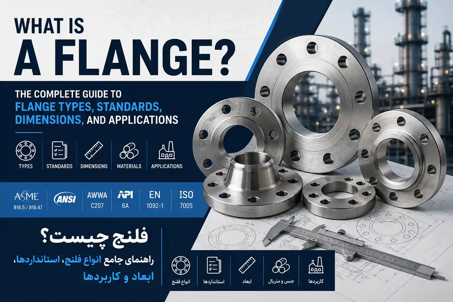
What Is a Pipe Flange? A Complete Engineering Guide to Types, Standards, Dimensions, Ratings, Gaskets, Bolting, and Selection
A pipe flange is far more than a simple metal ring with bolt holes. It is a precision-engineered component that forms the foundation of detachable, pressure-containing joints in piping systems across oil and gas, petrochemical, power generation, water treatment, and industrial facilities worldwide.
Unlike a permanent welded connection, a flanged joint is designed to be assembled and disassembled repeatedly without cutting the pipe. This makes flanges indispensable for applications requiring maintenance access, equipment isolation, periodic inspection, system modification, or component replacement.
However, the reliability of a flanged connection depends on far more than the flange alone. A properly engineered joint is a system comprising:
- The flange and its mating flange
- The gasket
- The bolting (studs, nuts, and washers)
- The pipe or equipment nozzle
- The sealing faces
- The assembly procedure used to establish and maintain bolt preload
A flange can have the correct nominal pipe size but still be unsuitable if its pressure-temperature rating, material, facing, bolt pattern, gasket arrangement, or dimensional standard does not match the mating component. This is why flange selection should never be based solely on outside diameter or bolt-hole count.
For engineers, procurement specialists, inspectors, and piping designers, the critical question is not simply "Which flange fits this pipe?" The more important question is:
"Which flange standard, type, material, rating, facing, gasket, and bolting arrangement provides a mechanically compatible and service-appropriate joint?"
This guide answers that question from first principles to practical engineering application.
Iran Etasal Asia — International Supply
Explore Iran Etasal Asia's international capabilities, export information, industrial products and project support for global buyers and contractors.
Explore International Services →Piping Engineering Tools
Use practical piping engineering calculators and technical tools to support pipe, fitting and piping-system calculations.
Explore Piping Tools →What Is a Pipe Flange?
A pipe flange is a mechanical component designed to provide a bolted, detachable connection between piping components, equipment, or valves. Depending on its design, the flange may be welded, threaded, slipped over the pipe, attached to a stub end, or otherwise integrated into a piping assembly.
Every flange typically contains:
- A central bore — must be compatible with the pipe or component to which it connects
- A flange body — provides structural strength
- A sealing face — the surface where the gasket is compressed
- Bolt holes — provide the means of applying and maintaining clamping force
- A hub or neck (on some types) — provides reinforcement and load transition
The entire assembly works by converting bolt tension into compressive force across the gasket and flange faces, creating a seal that prevents fluid leakage under operating conditions.
Why Flanges Are Used
Flanged connections are particularly valuable when a piping system requires frequent or planned disassembly. Typical applications include:
- Pumps and compressors
- Valves and control devices
- Pressure vessels and tanks
- Heat exchangers
- Water treatment systems
- Process piping in oil, gas, and chemical plants
- Utility piping systems
- Large-diameter water transmission pipelines
- Power generation facilities
A welded joint is generally permanent. A flanged joint is deliberately designed to be separable. That distinction is one of the main reasons flanges remain widely used despite the availability of welded and other connection technologies.
How a Flanged Joint Works
A flange connection creates a controlled mechanical interface. The basic sequence is:
Flange → gasket → mating flange → bolts → preload → gasket compression → sealing
When bolts are tightened, they generate tensile force in the bolts and compressive force across the flange faces. The gasket fills microscopic irregularities between the mating sealing surfaces. The objective is to maintain sufficient gasket stress under all operating conditions to prevent leakage.
This means that flange performance is not determined by flange dimensions alone. A flange can be dimensionally correct but still leak because of:
- Inadequate or excessive bolt preload
- Incorrect gasket selection
- Damaged flange faces
- Flange misalignment
- Uneven tightening
- Unsuitable temperature or chemical incompatibility
- Incorrect bolt material
- Inadequate installation control
Main Components of a Flanged Connection
A typical flanged joint contains several components that must be considered as one engineering system.
Flange
The flange provides the structural connection and transfers mechanical loads between the connected components.
Gasket
The gasket provides the primary sealing function. Its selection depends on pressure, temperature, fluid, chemical compatibility, flange facing, bolt load, installation conditions, and applicable standards. Gaskets are governed by ASME B16.20 (metallic) and ASME B16.21 (nonmetallic) [citation:9].
Bolting
Bolts or studs provide the clamping force required to compress the gasket. Bolting selection must consider strength, temperature, corrosion environment, compatibility with flange material, applicable code requirements, and installation procedure.
Pipe or Equipment Nozzle
The flange transfers load into the connected pipe, vessel nozzle, valve, or other component. This is particularly important in equipment connections because excessive external loads can affect equipment integrity.
Flange Standards: The Foundation of Compatibility
A flange standard establishes dimensional and technical requirements that allow compatible components to be specified and manufactured consistently. Standards may define items such as dimensions, pressure-temperature ratings, materials, tolerances, bolt-hole arrangements, marking, testing, facing requirements, and other design or manufacturing provisions.
Understanding which standard applies is fundamental to proper flange selection.
ASME B16.5 — The Industry Workhorse
ASME B16.5 is the most widely recognized flange standard in process and industrial piping [citation:1][citation:12]. It covers pipe flanges and flanged fittings from NPS 1/2 through NPS 24, including rating classes 150, 300, 400, 600, 900, 1500, and 2500. The standard addresses pressure-temperature ratings, materials, dimensions, tolerances, marking, testing, and methods of designating openings [citation:7].
B16.5 is limited to flanges and flanged fittings made from cast or forged materials, and blind flanges and certain reducing flanges made from cast, forged, or plate materials. It also includes requirements and recommendations regarding flange bolting, flange gaskets, and flange joints [citation:7].
The standard is intended to be used with other ASME standards, including the B31 piping codes [citation:12].
ASME B16.47 — Large-Diameter Flanges
For nominal pipe sizes above NPS 24, ASME B16.47 becomes the governing standard. It covers large-diameter steel flanges from NPS 26 through NPS 60, addressing pressure-temperature ratings, materials, dimensions, tolerances, marking, and testing. B16.47 has two series: Series A and Series B, with different bolt patterns [citation:13].
AWWA C207 — Waterworks Flanges
AWWA C207 addresses steel pipe flanges for waterworks service from 4 through 144 inches [citation:13]. It uses classes designated B, D, E, and F, which differ conceptually from the ASME pressure-class system. AWWA flanges are not interchangeable with ASME flanges without verification; dimensions, gasket sizing, and bolt patterns can differ significantly [citation:13].
MSS SP-44 — Pipeline Flanges
MSS SP-44 covers steel pipeline flanges and is particularly relevant for high-strength pipeline applications. For NPS 10 and smaller, SP-44 references ASME B16.5 for dimensional and tolerance requirements [citation:9].
Main Types of Pipe Flanges
The most commonly encountered flange types include:
- Welding Neck (WN)
- Slip-On (SO)
- Blind (BL)
- Socket Weld (SW)
- Threaded (TH)
- Lap Joint (LJ)
- Orifice
- Reducing
- Long Welding Neck
The appropriate type depends on pressure, temperature, pipe size, material, service, cyclic loading, corrosion, maintenance requirements, fabrication method, and governing standard [citation:8][citation:14].
Welding Neck Flange
The welding neck flange has a long tapered hub designed to be butt-welded to the pipe. The tapered hub provides reinforcement and allows a smooth stress transition from the flange to the pipe [citation:8]. This makes it ideal for high-pressure, high-temperature, cyclic, and critical services. The internal bore is matched to the pipe ID, preventing flow turbulence and erosion at the joint [citation:8].
Slip-On Flange
A slip-on flange fits over the outside of the pipe and is welded with two fillet welds (inside and outside). While less durable than welding neck flanges—having approximately two-thirds less calculated strength under internal pressure and one-third the fatigue life—they are more economical and easier to align [citation:8]. They are suitable for low- to medium-pressure applications [citation:14].
Blind Flange
A blind flange has no central bore and is used to close the end of a piping system or equipment nozzle. It serves purposes such as line isolation, pressure testing, equipment isolation, and future connection points. Blind flanges can experience significant pressure-induced forces, so their selection must consider pressure rating, material, thickness, gasket, and bolting [citation:14].
Socket Weld Flange
Socket weld flanges are designed for smaller-diameter, high-pressure piping (typically NPS 2 and smaller). The pipe is inserted into a socket and secured with a single fillet weld [citation:8]. They require a 1/16-inch gap between the pipe end and socket shoulder to allow for thermal expansion [citation:8]. Their fatigue strength is approximately 50% greater than slip-on flanges [citation:8].
Threaded Flange
Threaded flanges attach to threaded pipe without welding. They are useful where welding is undesirable or impractical, such as in hazardous areas or firefighting systems [citation:14]. However, they are generally limited to low-pressure, non-critical services due to leakage potential through threads [citation:8][citation:14].
Lap Joint Flange
A lap joint flange is used with a separate stub end. The flange itself is not wetted by the process fluid, making it suitable for corrosive services where expensive alloys would otherwise be required [citation:8][citation:14]. This configuration also allows for easy alignment of bolt holes without rotating the pipe.
Flange Facing Types: The Sealing Interface
The sealing face is one of the most important features of a flange. The facing must match the intended gasket and mating component. Common facing arrangements include:
- Raised Face (RF): The most common facing in process piping. The raised area provides concentrated gasket seating pressure [citation:10][citation:14].
- Flat Face (FF): The entire face is flat. Typically used with cast iron flanges (ASME B16.1) and low-pressure applications where full-face gaskets are required [citation:10][citation:14].
- Ring Type Joint (RTJ): Uses a metallic ring gasket seated in a machined groove. Preferred for high-pressure and high-temperature services [citation:10][citation:14].
- Tongue & Groove (T&G) and Male & Female (M&F): Confined gasket designs that provide self-centering and are used in specific applications [citation:10].
Flange Face Finish and Roughness
The surface finish of the flange face is critical for gasket performance. ASME B16.5 specifies concentric serrated finishes as the standard [citation:10]. Gasket type dictates the required roughness (AARH):
| Gasket Type | Recommended AARH (Ra) | Face Type |
|---|---|---|
| Spiral Wound (SWG) | 125–250 μin (3.2–6.3 μm) | RF |
| Compressed Non-Asbestos (CNAF) | 125–250 μin (3.2–6.3 μm) | RF/FF |
| Flexible Graphite | 63–125 μin (1.6–3.2 μm) | RF |
| Solid PTFE | 63–125 μin (1.6–3.2 μm) | RF/FF |
| RTJ Metallic Rings | 63 μin (1.6 μm) maximum | RTJ Groove |
Flange Pressure Classes: Understanding the Numbers
Pressure classes (also called ANSI classes) are one of the most misunderstood aspects of flange selection. ASME flange classes include 150, 300, 400, 600, 900, 1500, and 2500 [citation:1]. However, the class number should not be interpreted as a direct maximum pressure in psi across all temperatures and materials.
"ANSI Class" derives from the American National Standards Institute, but the term is more colloquial than official. The standard itself is ASME B16.5 [citation:4]. The rating basis for Class 150 flanges was developed in the ANSI B16.5-1973 publication, birthing what is known as ANSI class [citation:4].
Why Class 300 Does Not Mean 300 psi
Pressure-temperature ratings are material- and temperature-dependent. For a given material group, allowable pressure decreases as temperature increases [citation:15].
| Temperature °F (°C) | Class 150 | Class 300 | Class 600 | Class 900 | Class 1500 | Class 2500 |
|---|---|---|---|---|---|---|
| -20 to 100 (-29 to 38) | 285 psig | 740 psig | 1,480 psig | 2,220 psig | 3,705 psig | 6,170 psig |
| 200 (93) | 260 | 675 | 1,350 | 2,025 | 3,375 | 5,625 |
| 400 (204) | 200 | 635 | 1,270 | 1,900 | 3,170 | 5,280 |
| 600 (316) | 140 | 550 | 1,095 | 1,640 | 2,735 | 4,560 |
| 750 (399) | 95 | 505 | 1,010 | 1,510 | 2,520 | 4,200 |
| 1,000 (538) | 20 | 170 | 340 | 510 | 845 | 1,410 |
Values for ASTM A105 / A350 LF2 (Material Group 1.1) from ASME B16.5-2020 [citation:15]
Key Rules for Pressure-Temperature Ratings
- Interpolation: For temperatures between tabulated values, linear interpolation is permitted [citation:15].
- Material Groups: Different ASTM materials are assigned to different material groups with separate rating tables [citation:15].
- Independence from Size: The PT rating applies equally to all flange sizes within a given class and material group [citation:15].
- Bolting and Gasket Assumptions: Published ratings assume appropriate bolting and gaskets. Non-standard components may reduce the effective rating [citation:15].
Gasket Selection: The Sealing Element
A gasket is the sealing element installed between mating flange faces. It compensates for surface imperfections and creates a barrier against leakage. Gasket selection must consider the flange face type, operating pressure and temperature, fluid chemistry, and project specifications [citation:5].
Gasket Compatibility with Flange Faces
| Flange Face | Compatible Gasket Types | Notes |
|---|---|---|
| Raised Face (RF) | Spiral wound (SWG), soft gaskets (ring type) | Most common in process piping [citation:5] |
| Flat Face (FF) | Full-face soft gaskets only | Used with cast iron flanges; never use SWG on FF [citation:5] |
| Ring Type Joint (RTJ) | RTJ metallic rings (R, RX, BX) | Metal-to-metal seal [citation:5] |
| Tongue & Groove / M&F | SWG (without outer ring) or flat gaskets | Confined gasket, self-centering [citation:5] |
Gasket Selection by Service
| Service Condition | Recommended Gasket | Standard |
|---|---|---|
| Class 150-300, ambient to 200°C | Soft gasket (graphite, PTFE, CNAF) | ASME B16.21 [citation:5] |
| Class 150-600, up to 450°C | Spiral wound (flexible graphite filler) | ASME B16.20 [citation:5] |
| Class 600-2500, high pressure/temp | RTJ gasket (oval or octagonal) | ASME B16.20 [citation:5] |
| Vacuum service | SWG with inner ring | ASME B16.20 [citation:5] |
| Cryogenic (below -46°C) | SWG with PTFE filler, or RTJ | Project-specific [citation:5] |
Bolting and Tightening: The Clamping System
Bolting is a structural part of the sealing system. Typical components include studs, nuts, and washers where specified. The required bolt load depends on the gasket, flange design, and service.
Torque and Preload Relationship
Torque is commonly used as an indirect method for controlling bolt preload. A simplified relationship is:
T = K × D × F
where T = torque, K = nut factor (typically 0.1-0.3, empirical value 0.2), D = nominal bolt diameter, and F = desired bolt preload [citation:11].
However, torque depends strongly on thread condition, lubrication, friction, washer condition, surface condition, bolt coating, and installation method. Therefore, a specified torque value should come from the applicable engineering procedure rather than a generic internet table.
Tightening Sequence
Flange bolts should be tightened in a controlled cross (star) pattern to distribute gasket compression uniformly [citation:6]. Per ASME PCC-1, the cross-pattern is mandatory for all flanged joints in pressure piping [citation:6].
| Number of Bolts | Tightening Order (bolt positions) |
|---|---|
| 4 bolts | 1-3-2-4 |
| 8 bolts | 1-5-3-7-2-6-4-8 |
| 12 bolts | 1-7-4-10-2-8-5-11-3-9-6-12 |
| 16 bolts | 1-9-5-13-3-11-7-15-2-10-6-14-4-12-8-16 |
Bolt numbering starts at the 12 o'clock position and increases clockwise [citation:6]
Number of Tightening Passes
| Pass | Target Torque | Purpose |
|---|---|---|
| Pass 1 | 20-30% of target | Initial snug to seat gasket and pull flanges together [citation:6] |
| Pass 2 | 50-70% of target | Intermediate load to compress gasket uniformly [citation:6] |
| Pass 3 | 100% of target (cross pattern) | Full target torque applied in cross-pattern sequence [citation:6] |
| Pass 4 | 100% of target (clockwise) | Final verification pass in clockwise order [citation:6] |
Flange Dimensions: What Matters Most
Important flange dimensions include:
- Outside Diameter (OD)
- Inside Diameter or Bore — Must match the pipe ID for bore-matched flanges
- Flange Thickness
- Bolt-Circle Diameter — The geometric location of bolts
- Number and Diameter of Bolt Holes
- Hub Dimensions (for welding neck flanges)
- Raised-Face Dimensions
- RTJ Groove Dimensions
Two flanges can have the same nominal pipe size but different bolt patterns if they belong to different standards or pressure classes. Therefore, nominal size alone is not sufficient for flange interchangeability.
Flange Selection Process: A Practical Engineering Workflow
A systematic approach ensures all critical parameters are considered:
Step 1 — Identify the Piping Service
Determine fluid, pressure, temperature, corrosion conditions, and hazard classification.
Step 2 — Identify Pipe Size
Determine NPS/DN, pipe outside diameter, wall thickness, and schedule.
Step 3 — Identify Governing Standard
Examples: ASME B16.5, ASME B16.47, AWWA C207, MSS SP-44, EN, DIN, JIS.
Step 4 — Select Flange Type
Examples: welding neck, slip-on, blind, socket weld, threaded, lap joint.
Step 5 — Select Rating
Consider design pressure, design temperature, material group, and applicable rating tables.
Step 6 — Select Facing
Examples: RF, FF, RTJ.
Step 7 — Select Material
Verify mechanical requirements, corrosion resistance, temperature capability, and welding compatibility.
Step 8 — Select Gasket
Confirm compatibility with fluid, temperature, pressure, and flange facing.
Step 9 — Select Bolting
Verify material, strength, temperature capability, compatibility, and installation method.
Step 10 — Verify Dimensions
Check OD, ID/bore, thickness, bolt circle, bolt holes, facing, and hub dimensions.
Common Flange Selection Mistakes
- Mistake: Selecting by nominal size only — Consequence: Incompatible bolt patterns or dimensions.
- Mistake: Assuming all Class 150 flanges are interchangeable — Consequence: Different standards have different dimensions.
- Mistake: Ignoring temperature — Consequence: Pressure ratings are pressure-temperature dependent [citation:15].
- Mistake: Selecting gasket after the flange — Consequence: Gasket should be considered as part of joint design.
- Mistake: Mixing standards without verification — Consequence: ASME, AWWA, EN, DIN, and JIS are not automatically interchangeable [citation:2][citation:13].
- Mistake: Using slip-on flanges for high-pressure steam — Consequence: Inadequate strength and fatigue life [citation:14].
- Mistake: Over-tightening causing flange warping — Consequence: Gasket damage and leakage [citation:14].
International Flange Terminology
For global procurement, understanding terminology in multiple languages is essential.
| English | Arabic | Russian |
|---|---|---|
| Pipe Flange | شفة الأنبوب / فلانشه | Фланец трубопровода |
| Flanged Connection | وصلة فلنجية | Фланцевое соединение |
| Welding Neck Flange | شفة عنق اللحام | Приварной встык фланец |
| Slip-On Flange | شفة منزلقة | Плоский приварной фланец |
| Blind Flange | شفة عمياء | Глухой фланец |
| Socket Weld Flange | شفة لحام مقبس | Фланец под приварку раструбом |
| Threaded Flange | شفة ملولبة | Резьбовой фланец |
| Raised Face (RF) | وجه مرتفع | Выступающий торец |
| Flat Face (FF) | وجه مستوٍ | Плоский торец |
| Ring Type Joint (RTJ) | وصلة حلقي | Соединение с кольцевой прокладкой |
| Gasket | حشية | Прокладка |
| Bolt Circle | دائرة مسامير التثبيت | Окружность расположения болтовых отверстий |
Frequently Asked Questions
What is a pipe flange?
A pipe flange is a mechanical component used to create a bolted, detachable connection between piping components, equipment, or valves.
What is the purpose of a flange?
Its primary purposes are connection, sealing, and controlled disassembly.
What is ASME B16.5?
ASME B16.5 is a standard covering pipe flanges and flanged fittings from NPS 1/2 through NPS 24, including dimensions, ratings, materials, tolerances, marking, and testing [citation:1][citation:12].
What is AWWA C207?
AWWA C207 covers steel pipe flanges for waterworks service from 4 through 144 inches [citation:13].
What is ASME B16.47?
ASME B16.47 covers large-diameter steel flanges from NPS 26 through NPS 60.
What does flange Class 150 mean?
It is an ASME pressure-class designation, not a universal statement that the flange is rated for exactly 150 psi under all conditions. The actual rating depends on material and temperature [citation:4][citation:15].
What is an RF flange?
RF means Raised Face, the most common facing in process piping [citation:14].
What is an FF flange?
FF means Flat Face, typically used with cast iron flanges and low-pressure applications [citation:14].
What is an RTJ flange?
RTJ means Ring Type Joint and uses a metallic ring gasket seated in a machined groove for high-pressure and high-temperature service [citation:14].
What is a blind flange?
A blind flange closes a pipe or equipment connection and has no central bore [citation:14].
What is a welding neck flange?
A welding neck flange has a tapered hub and is butt-welded to the pipe. It provides reinforcement and stress transition [citation:8].
What is a slip-on flange?
A slip-on flange fits over the pipe and is normally welded with two fillet welds [citation:8].
Are ASME and AWWA flanges interchangeable?
Not automatically. Their standards have different scopes, dimensions, and rating systems [citation:13].
Can I select a flange only by pipe size?
No. Standard, rating, facing, material, bore, and bolt pattern must also be verified.
Does flange temperature affect pressure rating?
Yes. Pressure-temperature ratings depend on the applicable standard and material group [citation:15].
Can any gasket be used with any flange?
No. Gasket selection must be compatible with the flange facing, fluid, pressure, temperature, and installation conditions [citation:5].
Why do flanges leak?
Common causes include incorrect gasket selection, uneven bolt preload, flange damage, misalignment, pipe strain, and improper assembly [citation:6].
Should a leaking flange simply be tightened?
Not necessarily. The root cause should be investigated and appropriate safety procedures followed.
What is a bolt circle?
It is the circular geometric pattern defining the location of flange bolt holes.
What standards are used for large-diameter flanges?
Depending on the application, standards such as ASME B16.47 and AWWA C207 may be relevant [citation:13].
Conclusion
A pipe flange is a deceptively simple component with a technically complex function. The flange itself is only one part of the joint. Reliable performance depends on the compatibility of the flange, gasket, bolting, pipe, equipment, installation, and operating conditions.
The first step in selecting a flange is not choosing a product from a catalog. It is defining the engineering requirements—service, pressure, temperature, pipe size, standard, flange type, rating, facing, material, gasket, bolting, and dimensional requirements.
ASME B16.5 remains a major reference for pipe flanges and flanged fittings within its defined size and rating scope. ASME B16.47 addresses large-diameter steel flanges. AWWA C207 addresses steel pipe flanges for waterworks service. MSS SP-44 provides another important reference for steel pipeline flanges.
The most important principle is simple: Never select a flange based on size alone. A technically correct flange satisfies the governing standard, dimensional requirements, pressure-temperature conditions, material requirements, sealing system, and installation requirements of the actual piping application.
For engineers and procurement professionals, this approach reduces leakage risk, improves compatibility, and supports safer, more reliable piping systems. For international buyers, the same engineering logic applies regardless of language—the terminology may change, but the engineering requirements remain the same.
Need Flanges for an Oil & Gas or Industrial Project?
For technical specifications, product availability, project requirements, or international supply inquiries, contact Iran Etasal Asia.
International Inquiry →Technical References & Standards
ASME B16.5
Pipe Flanges and Flanged Fittings: NPS 1/2 through NPS 24 — Dimensions, ratings, materials, tolerances, marking, testing [citation:1][citation:12].
ASME OfficialAWWA C207
Steel Pipe Flanges for Waterworks Service: 4 through 144 inches [citation:13].
AWWA OfficialASME PCC-1
Guidelines for Pressure Boundary Bolted Flange Joint Assembly — Tightening procedures and gasket seating [citation:6].
ASME OfficialASME B16.20
Metallic Gaskets for Pipe Flanges — Ring-joint and spiral-wound gasket dimensions [citation:5][citation:9].
ASME OfficialRelated Internal Resources
- International Products & Export Information
- Piping Engineering Tools & Calculators
- ASME B16.9 and Butt-Weld Fittings
- ASME B16.25 Butt-Welding Ends
- SCH 40 vs SCH 80 Comparison
- Detecting Fake Welding Fittings
- Welding Fittings Procurement Guide
- Welded Joint Leak Case Study
- Stress Analysis of Elbows, Tees & Reducers
- Steel Pipeline Installation Best Practices
- How to Read Piping Isometric Drawings
- Long Radius vs Short Radius Elbows
- Seamless vs Welded Elbows