
Stress Analysis, Strain Distribution, and Mechanical Behavior of Steel Elbows, Tees, and Reducers Under Internal Pressure and Operational Loads

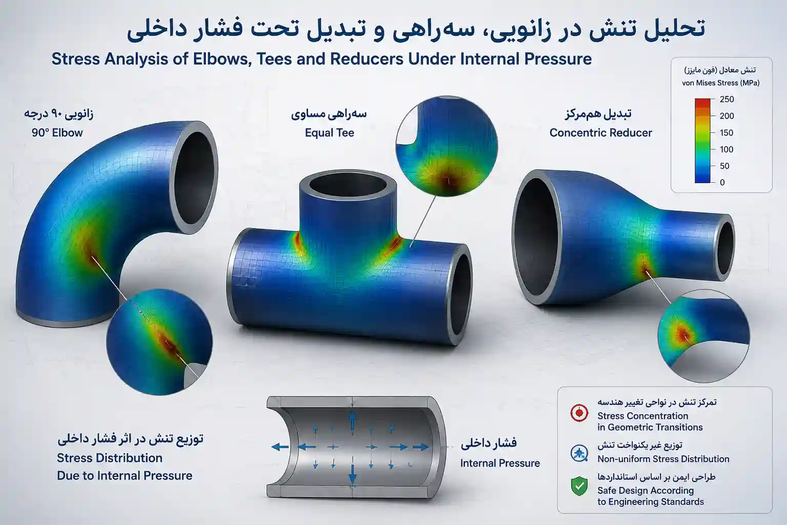
Stress Analysis, Strain Distribution, and Mechanical Behavior of Steel Elbows, Tees, and Reducers
Comprehensive engineering analysis of stress distribution, strain behavior, and mechanical performance of steel butt weld fittings under internal pressure and operational loads per ASME B31.3 and ASME B16.9
Table of Contents
1. Introduction
The safe and reliable operation of industrial piping systems depends on a thorough understanding of the stress distribution, strain behavior, and mechanical performance of its components under internal pressure and operational loads. Among these components, steel butt weld fittings—including elbows, tees, and reducers—are critical elements that introduce geometric discontinuities, leading to complex stress states that must be carefully analyzed to prevent failure.
This comprehensive engineering analysis examines the stress analysis, strain distribution, and mechanical behavior of steel elbows, tees, and reducers under internal pressure and operational loads, based on established standards including ASME B31.3 (Process Piping), ASME B16.9 (Factory-Made Wrought Steel Butt Welding Fittings), and ASME Section VIII. The analysis draws upon authoritative engineering references, including ASME pressure vessel and piping codes, ASTM material standards, and peer-reviewed technical literature.
Key Principle: The geometric discontinuities introduced by fittings create localized stress concentrations that must be accounted for in piping system design. Proper stress analysis ensures that fittings withstand internal pressure, thermal expansion, and external loads without exceeding allowable stress limits.
The analysis covers the fundamental principles of stress analysis, including hoop stress, longitudinal stress, and equivalent stress per ASME B31.3. It then examines the specific stress distribution in elbows (including the effects of bend radius and ovality), tees (including branch connection stress intensification), and reducers (including transition zone stress concentrations). The mechanical behavior of these fittings under operational loads is evaluated, including the effects of pressure, temperature, and external loading.
For engineers designing or evaluating piping systems, understanding these stress characteristics is essential for ensuring pressure integrity, fatigue resistance, and long-term reliability. This guide provides the technical foundation required to perform accurate stress analysis and make informed engineering decisions.
2. Fundamentals of Stress Analysis
2.1 Basic Stress Equations
The fundamental stress analysis of piping components under internal pressure is governed by the following equations, per ASME B31.3:
Hoop Stress (Circumferential): σh = (P × D) / (2 × t)
Longitudinal Stress: σl = (P × D) / (4 × t)
Equivalent Stress (von Mises): σe = √(σh² - σh × σl + σl²)
Where:
- P = Internal design pressure (MPa or psi)
- D = Outside diameter of pipe (mm or inches)
- t = Wall thickness (mm or inches)
- σh = Hoop stress (MPa or psi)
- σl = Longitudinal stress (MPa or psi)
- σe = Equivalent von Mises stress (MPa or psi)
The allowable stress values for pipe materials are established in ASME Section II, Part D and are based on the material's yield strength, tensile strength, and creep rupture strength at the design temperature. For carbon steel Grade B (ASTM A53, A106, API 5L), the allowable stress at ambient temperature is approximately 137.9 MPa (20,000 psi) per ASME B31.3.
2.2 Stress Concentration Factors
Fittings introduce geometric discontinuities that create localized stress concentrations. The Stress Concentration Factor (SCF) is a multiplier applied to the nominal stress to account for these localized increases. Per ASME B31.3, SCF values for common fittings are:
| Fitting Type | SCF (Intrados) | SCF (Extrados) | SCF (Crown) |
|---|---|---|---|
| Elbow, LR (R/D = 1.5) | 2.5 – 3.0 | 1.5 – 2.0 | 1.0 – 1.2 |
| Elbow, SR (R/D = 1.0) | 3.5 – 4.5 | 2.0 – 2.5 | 1.2 – 1.5 |
| Tee (Branch Connection) | — | — | 2.0 – 3.0 |
| Reducer (Concentric) | — | — | 1.5 – 2.0 |
The SCF values are used in fatigue analysis and in the design of piping systems subjected to cyclic loading. Higher SCF values indicate greater stress concentration and reduced fatigue life.
3. Stress Analysis of Elbows
Elbows are the most common type of pipe fitting, used to change the direction of flow in a piping system. The stress distribution in an elbow is more complex than in straight pipe due to the curved geometry, which creates bending stresses, ovalization, and localized stress concentrations.
3.1 Stress Distribution in Elbows
Under internal pressure, an elbow experiences:
- Hoop Stress: Circumferential stress that is highest at the intrados (inside radius) and lowest at the extrados (outside radius).
- Longitudinal Stress: Axial stress that is uniform across the cross-section but affected by bending due to pressure thrust.
- Bending Stress: Caused by the pressure thrust acting on the elbow, creating a moment that tends to straighten the elbow.
- Ovalization: Deformation of the circular cross-section into an oval shape, which increases stress at the intrados and extrados.
According to ASME B31.3, the pressure design of elbows must account for the flexibility factor and stress intensification factor (SIF) to ensure adequate strength. The flexibility factor for a long-radius elbow (R/D = 1.5) is approximately 1.5 times that of a straight pipe, while the SIF ranges from 2.5 to 3.0 at the intrados.
3.2 Long Radius vs. Short Radius Elbows
The bend radius significantly affects the stress distribution in elbows. Long Radius (LR) elbows (R/D = 1.5) have a smoother bend, resulting in:
- Lower stress concentration factors (SCF 2.5 – 3.0 versus 3.5 – 4.5 for SR)
- Reduced ovalization during forming and under pressure
- Lower pressure drop and reduced erosion
- Longer fatigue life under cyclic loading
Short Radius (SR) elbows (R/D = 1.0) have a tighter bend, which results in:
- Higher stress concentration at the intrados
- Greater ovalization and wall thinning at the extrados
- Higher pressure drop and increased erosion
- Reduced fatigue life compared to LR elbows
For critical applications or high-pressure systems, ASME B31.3 recommends the use of long-radius elbows to minimize stress concentrations and ensure long-term reliability. For more detailed guidance, refer to the LR vs SR Elbow Selection Guide.
3.3 Wall Thinning and Ovality
During the manufacturing process, elbows experience wall thinning at the extrados (outside radius) due to tensile stretching and wall thickening at the intrados (inside radius) due to compressive forces. This wall thickness variation, combined with ovalization, creates non-uniform stress distribution:
- Extrados: Higher stress due to reduced wall thickness and higher bending stress
- Intrados: Lower stress due to increased wall thickness but higher stress concentration
- Crown: Intermediate stress with minimal wall thickness variation
Per ASME B16.9, the minimum wall thickness at any point in a fitting must be at least 87.5% of the nominal wall thickness of the connected pipe. However, for elbows, the actual minimum thickness may be lower at the extrados, requiring additional thickness in the pipe design to compensate.
4. Stress Analysis of Tees
Tees are used to create branch connections in piping systems, allowing flow to be diverted from the main run to a branch line. The intersection of the branch and main run creates a complex stress state with high stress concentrations at the crotch (the intersection point between the branch and the main pipe).
4.1 Stress Distribution in Tees
Under internal pressure, a tee experiences:
- Hoop Stress in Main Run: Similar to straight pipe but affected by the branch opening
- Hoop Stress in Branch: Circumferential stress in the branch pipe
- Localized Stresses at the Crotch: High stress concentration due to the geometric discontinuity
- Bending Stresses: Caused by pressure thrust and external loads on the branch
The highest stress in a tee typically occurs at the crotch corner, where the branch meets the main run. The stress concentration factor for a tee branch connection, per ASME B31.3, ranges from 2.0 to 3.0, depending on the branch-to-run diameter ratio and the wall thickness.
4.2 Equal vs. Reducing Tees
Equal tees have the same diameter for the main run and the branch, resulting in:
- Lower stress concentration than reducing tees for the same diameter
- More uniform stress distribution across the intersection
- Simpler fabrication and lower cost
Reducing tees have a smaller branch diameter than the main run, resulting in:
- Higher stress concentration at the crotch due to the diameter change
- Need for additional reinforcement to compensate for the branch opening
- Higher fabrication complexity and cost
4.3 Branch Reinforcement
Per ASME B31.3, branch connections must be reinforced to compensate for the material removed from the main run to create the branch opening. The reinforcement area required is calculated based on the branch diameter, wall thickness, and the pressure design conditions. Reinforcement can be provided by:
- Increasing the wall thickness of the main run and branch
- Adding a reinforcement pad (weldolet or sockolet)
- Using a forged tee with integral reinforcement
For detailed tee dimensions and design, refer to the Tee Dimensions Guide.
5. Stress Analysis of Reducers
Reducers are used to transition between different pipe diameters, allowing flow to be directed from a larger pipe to a smaller one (or vice versa). The change in diameter creates stress concentrations at the transition zone and may require additional reinforcement.
5.1 Stress Distribution in Reducers
Under internal pressure, a reducer experiences:
- Hoop Stress: Varies along the length of the reducer, with higher stress in the smaller diameter section
- Longitudinal Stress: Created by the pressure thrust acting on the reducer, with a net axial force due to the diameter change
- Bending Stress: Caused by the pressure thrust and any external loads
- Stress Concentration at the Transition: Localized stress at the point where the diameter changes
The stress concentration factor for a reducer, per ASME B31.3, ranges from 1.5 to 2.0, depending on the diameter ratio and the transition geometry.
5.2 Concentric vs. Eccentric Reducers
Concentric reducers have a common centerline, with the diameter change occurring uniformly around the circumference. This results in:
- Symmetric stress distribution
- Lower stress concentration than eccentric reducers
- Preference for vertical piping systems and pump suction lines
Eccentric reducers have a flat side, with the diameter change occurring asymmetrically. This results in:
- Asymmetric stress distribution with higher stress on the flat side
- Higher stress concentration than concentric reducers
- Preference for horizontal piping to maintain a continuous bottom elevation
For detailed reducer dimensions and design, refer to the Reducer Dimensions Guide.
6. Strain Distribution Analysis
Strain distribution is closely related to stress distribution, with the relationship defined by the material's stress-strain curve. Under internal pressure and operational loads, fittings experience both elastic and plastic strain, depending on the stress level relative to the material's yield strength.
6.1 Strain in the Elastic Range
In the elastic range, strain is proportional to stress per Hooke's Law:
- Longitudinal Strain: εl = σl / E
- Hoop Strain: εh = σh / E
- Shear Strain: γ = τ / G
Where E is the modulus of elasticity and G is the shear modulus. For carbon steel at ambient temperature, E ≈ 200 GPa (29,000 ksi).
6.2 Strain in the Plastic Range
When the equivalent stress exceeds the material's yield strength, plastic strain occurs. The plastic strain is determined by the material's strain-hardening behavior, which depends on the manufacturing process and heat treatment. For carbon steel fittings, the yield strength (ASTM A234 WPB) is approximately 240 MPa (35,000 psi).
In fittings, plastic strain is most likely to occur at stress concentration points, such as:
- Elbow intrados: Highest stress concentration
- Tee crotch: High stress due to branch intersection
- Reducer transition: Stress concentration at diameter change
6.3 Strain and Fatigue
Repeated cyclic loading causes low-cycle fatigue when plastic strain occurs, and high-cycle fatigue when only elastic strain is present. The fatigue life of a fitting is determined by the strain-life curve (ε-N curve), which is based on material testing.
Per ASME B31.3, fatigue analysis is required for piping systems with significant cyclic loading, such as those subjected to thermal cycles, pressure fluctuations, or external vibrations. The stress intensification factors (SIF) and flexibility factors provided in the code are used in fatigue analysis to determine the fatigue life of fittings.
7. Mechanical Behavior Under Operational Loads
The mechanical behavior of steel elbows, tees, and reducers under operational loads is a critical factor in ensuring the safety and reliability of piping systems. Operational loads include internal pressure, thermal expansion, external forces, and cyclic loading.
7.1 Pressure-Induced Behavior
Under internal pressure, fittings experience both hoop and longitudinal stresses that must be kept within allowable limits. The pressure design of fittings per ASME B31.3 requires that the equivalent stress (von Mises) does not exceed the allowable stress at the design temperature.
7.2 Thermal Expansion Effects
Thermal expansion and contraction create thermal stresses in piping systems. Fittings, as geometric discontinuities, experience higher thermal stresses than straight pipe due to the localized stress concentration.
- Elbows: Thermal expansion creates bending stresses at the intrados and extrados
- Tees: Thermal expansion creates bending and shear stresses at the branch connection
- Reducers: Thermal expansion creates longitudinal and bending stresses at the transition zone
7.3 External Loads and Supports
External loads, including weight, wind, and seismic forces, must be considered in piping system design. Proper support placement is essential to limit these loads to acceptable levels. Per ASME B31.3, the stress from external loads must be combined with pressure and thermal stresses in the design evaluation.
7.4 Fatigue Behavior
Fatigue failure is a significant concern for piping systems subjected to cyclic loading. The fatigue life of fittings is influenced by:
- Stress concentration factors (SCF): Higher SCF reduces fatigue life
- Material properties: Higher ductility and toughness improve fatigue resistance
- Surface finish: Smooth surfaces reduce fatigue crack initiation
- Residual stresses: Compressive residual stresses improve fatigue life
For critical applications, fracture mechanics analysis may be required to evaluate the acceptable flaw size and remaining life of fittings. This is particularly important for high-pressure or high-temperature services.
8. Comparison Tables
Table 1: Stress Concentration Factors (SCF) by Fitting Type
| Fitting Type | SCF (Intrados/Crotch) | SCF (Extrados) | SCF (Crown) | Typical Fatigue Life Factor |
|---|---|---|---|---|
| Elbow, LR (R/D=1.5) | 2.5 – 3.0 | 1.5 – 2.0 | 1.0 – 1.2 | 1.0 |
| Elbow, SR (R/D=1.0) | 3.5 – 4.5 | 2.0 – 2.5 | 1.2 – 1.5 | 0.5 – 0.7 |
| Tee (Equal) | 2.0 – 2.5 | — | 1.5 – 2.0 | 0.7 – 0.9 |
| Tee (Reducing) | 2.5 – 3.5 | — | 2.0 – 2.5 | 0.5 – 0.7 |
| Reducer (Concentric) | 1.5 – 2.0 | — | 1.2 – 1.5 | 0.8 – 0.9 |
| Reducer (Eccentric) | 2.0 – 2.5 | — | 1.5 – 2.0 | 0.7 – 0.8 |
Table 2: Recommended Fitting Selection Based on Stress and Service Conditions
| Service Condition | Recommended Elbow | Recommended Tee | Recommended Reducer |
|---|---|---|---|
| High Pressure (> 100 bar) | LR Elbow (R/D=1.5) | Equal Tee with reinforcement | Concentric Reducer |
| High Temperature (> 400°C) | LR Elbow (R/D=1.5) | Equal Tee with PWHT | Concentric Reducer |
| Cyclic Service (Thermal) | LR Elbow (R/D=1.5) | Equal Tee with reinforcement | Concentric Reducer |
| Corrosive Service | LR Elbow (R/D=1.5) | Equal Tee, corrosion allowance | Concentric Reducer |
| Space-Constrained | SR Elbow (R/D=1.0) | Reducing Tee (if needed) | Eccentric Reducer |
| Low Pressure / General | LR or SR Elbow | Equal Tee | Concentric Reducer |
9. References
ASME Standards
- ASME B31.3 — Process Piping
- ASME B16.9 — Factory-Made Wrought Steel Butt Welding Fittings
- ASME Section II — Materials (Parts A & B)
- ASME Section VIII — Pressure Vessels
- ASME B31.1 — Power Piping
ASTM Standards
- ASTM A234 — Carbon and Alloy Steel Fittings
- ASTM A403 — Austenitic Stainless Steel Fittings
- ASTM A420 — Low-Temperature Carbon Steel Fittings
- ASTM A370 — Mechanical Testing
- ASTM E8 — Tensile Testing
API Standards
- API 5L — Line Pipe
- API 579 — Fitness-for-Service
Other Standards
- MSS SP-75 — High-Test Fittings
- NACE MR0175 — Sour Service
Engineering References
- ASM International — Metals Handbook
- TWI — Welding and Joining Technology
- NIST — Metallurgical Standards
Need Expert Stress Analysis Support for Your Piping System?
Iran Etesal Asia is a leading manufacturer of high-quality steel butt weld fittings, serving the oil and gas, petrochemical, power generation, and water treatment industries worldwide. Our products are manufactured in accordance with ASME, ASTM, API, and MSS standards, with full traceability and rigorous quality control.
We offer international cooperation, OEM manufacturing, export supply, and technical consultation to EPC contractors, distributors, industrial buyers, and project procurement teams.